GE M
EDICAL
S
YSTEMS
D
IRECTION
FK091075, R
EVISION
04
V
IVID
3N P
RO
/E
XPERT
S
ERVICE
M
ANUAL
Chapter 8 Replacement Procedures
8-125
8-8-2-5
Sony VCR Removal Procedure
1.) Remove the Connectors Panels Cover as described in
8-2-5-3 "Connector Panels Cover Removal
Procedure" on page 8-8
.
2.) If optional shelf is present, refer to the
8-8-4-5 "Color Video Printer Removal - Procedure 1" on page
8-139
.
3.) Release the B/W printer by undoing the fastening belt around it (together with the VCR, if present).
4.) Disconnect the
RS
-
232C
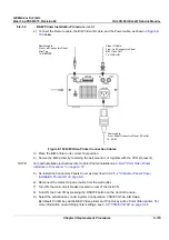
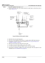
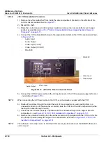
cable, the Audio and S-Video IN and OUT cables, and Power cord from
VCR’s rear as shown in
Figure 8-108 "Sony VCR Connection Cables" on page 8-124
.
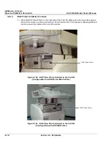
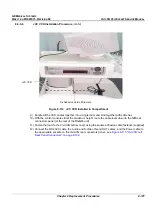
5.) Remove the VCR from the
left
side of the Vivid 3N ultrasound unit (taking it out from below the
control console and from beside the B/W printer, if present) - refer to
Figure 8-106 "Video Cassette
Recorder (VCR) Installed in the Vivid 3N Ultrasound Unit Configuration with UP2950 Printer" on
page 8-123
.


