GE M
EDICAL
S
YSTEMS
D
IRECTION
FK091075, R
EVISION
04
V
IVID
3N P
RO
/E
XPERT
S
ERVICE
M
ANUAL
Chapter 8 Replacement Procedures
8-133
8-8-3-7
JVC VCR Removal Procedure
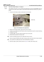
1.) Remove the Connectors Panel cover as shown in
8-2-5-3 "Connector Panels Cover Removal
Procedure" on page 8-8
.
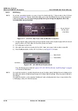
2.) Disconnect the RS-232C cable, the Audio and S-Video IN and OUT cables, and the Power cable
from the Vivid 3N rear connectors panel - see
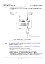
Figure 8-115 "Vivid 3N Left Rear Panel Connectors"
on page 8-132
.
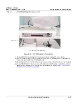
3.) Remove the adhesive velcro strip from the edge of the side compartment on the
left
side of the Vivid
3N ultrasound unit (refer to
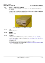
Figure 8-114 "JVC VCR Installed in Compartment" on page 8-131
).
4.) Slide the VCR partially out of the compartment, carefully easing the attached cables with it.
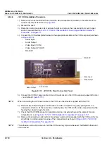
5.) Disconnect the RS-232C cable, the Audio and S-Video IN and OUT cables from VCR rear
connectors panel (refer to
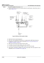
Figure 8-113 "JVC VCR - Rear Connectors Panel" on page 8-130
).
6.) Disconnect the AC power cable from the AC Input socket on the VCR rear panel (upper
left
corner).
7.) When all cables are disconnected, remove the VCR completely from the Vivid 3N ultrasound unit.

