GE M
EDICAL
S
YSTEMS
D
IRECTION
FK091075, R
EVISION
04
V
IVID
3N P
RO
/E
XPERT
S
ERVICE
M
ANUAL
Chapter 8 Replacement Procedures
8-151
8-8-5-4 Sony UP-21MD Color Video Printer Installation - Procedure1
(cont’d)
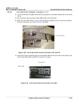
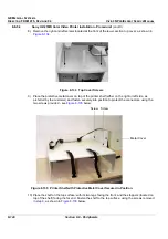
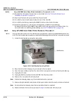
20.)Position the Color Video Printer against the rubber stoppers at the rear of the shelf, and against the
metal protective cover on the side (making sure that the connectors are not exposed).
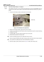
21.)Connect the two plastic buckles and tighten the belts. Verify that the UP-21MD Color Video Printer
is secure.
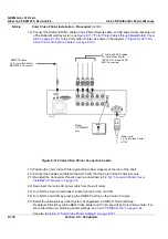
Figure 8-139 Sony UP-21MD Color Video Printer Connection Cables
R, G, B and SYNC cables:
To: UP-21MD Color Video Printer
INPUT R, G/G-SYNC, B and SYNC
BNC Connectors
REMOTE cable:
To: UP-21MD Color Video
Printer REMOTE 2 Connector
NTSC/PAL
selector
Power cord:
To: UP-21MD Color
Video Printer AC IN

