GE M
EDICAL
S
YSTEMS
D
IRECTION
FK091075, R
EVISION
04
V
IVID
3N P
RO
/E
XPERT
S
ERVICE
M
ANUAL
Chapter 8 Replacement Procedures
8-149
8-8-5-4 Sony UP-21MD Color Video Printer Installation - Procedure1
(cont’d)
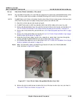
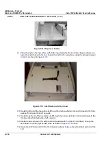
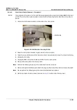
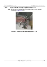
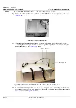
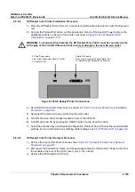
Figure 8-136 Shelf Fastened to Top Cover
11.)Route the end of one of the top surface securing belts down through the narrow
left
slot in the shelf
(closest to the front), then thread it below the shelf,
backwards
and
upwards
through the slot at the
rear of the shelf. Leave the opposite end of the belt (with the plastic buckle [female end] attached)
dangling towards the front, as shown in
Figure 8-135
and
Figure 8-136
on page 8-149.
12) Repeat
step 11
to thread the second belt in position through the slot on the
right
.
13) Attach the male end of the two plastic buckles to each of the belt ends protruding from the rear
right
and
left
slots.
14) Return the color printer and VCR to their original positions, between the left and right sections of the belt.
15) Lock the belt buckles to tighten the shelf to the top surface. Verify that the printer and VCR are secure.
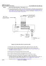
16.)Re-connect the previously-disconnected Color Printer and VCR cables.
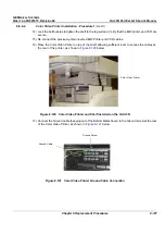
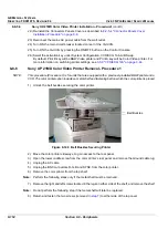
17) Place the UP-21MD Color Video Printer on top of the shelf, as shown in
Figure 8-137
below.
Figure 8-137 Sony UP-21MD Color Video Printer and Shelf Installed on the Vivid 3N
UP-21MD
Color Video Printer

