GE M
EDICAL
S
YSTEMS
D
IRECTION
FK091075, R
EVISION
04
V
IVID
3N P
RO
/E
XPERT
S
ERVICE
M
ANUAL
8-86
Section 8-5 - Back End Parts Replacement
8-5-12-6
BEP2 - ECG Module Installation Procedure
NOTE:
BEP2 refers to a Pentium 4-based BEP (newer type).
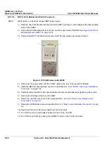
1.) Slide the new ECG Module into the front of the BEP, pushing it in until it aligns with other modules
at the front of BEP.
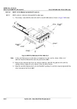
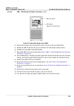
2) Secure the ECG Module with four screws, two from each side of the BEP (see
Figure 8-72 "ECG
Module Removal- BEP2" on page 8-85
).
3.) Replace the BEP Front Panel and secure it with the two screws previously removed.
4) Reconnect the power cable and the COM 2 cable to the rear of the new ECG Module.
5) Install the BEP left and right side covers, as described in
8-5-3-4 "BEP2 - Side Cover Installation
Procedure" on page 8-64
.
6.) Carefully return the BEP to its original location and secure all brackets by tightening the screws.
7) Reconnect all cables at the rear of the BEP.
8) Return the Vivid 3N rear cover to its original position - see
8-2-4 "Rear Cover Replacement
Procedures" on page 8-7
.
9)
Return the Vivid 3N side covers, as described in
8-2-2-4 "Side Covers Installation Procedure" on page
8-4
.
10) Reconnect the mains AC power cable from the wall outlet.
11) Turn ON the main circuit breaker located on rear of the Vivid 3N.
12) Turn ON the Vivid 3N by pressing the ON/OFF button on the Control Console.
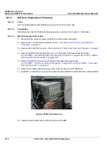
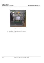
Figure 8-73 ECG Module inside BEP2

