background image

Chapter 1  System Management
  1.8  Network Management

ETERNUS Web GUI User’s Guide (Settings)

Copyright 2015 FUJITSU LIMITED

P2X0-1270-13ENZ0

143

6

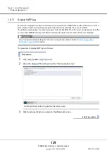
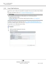
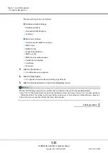
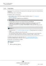
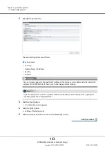
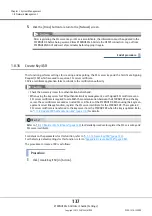
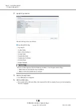
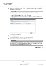
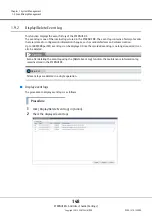
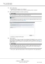
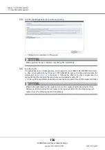
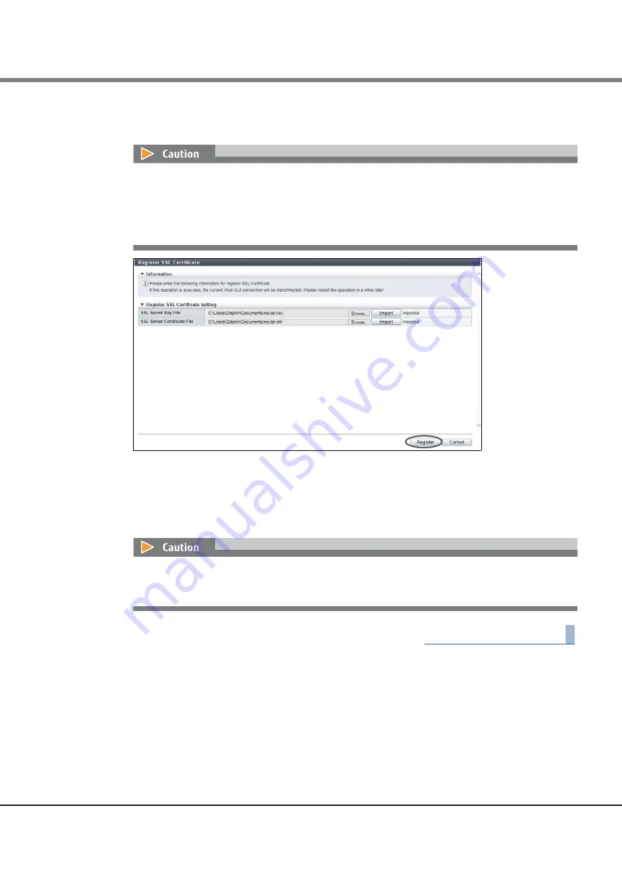
Confirm that the "SSL server key file" and the "SSL server certificate file" have been imported, 
and click the [Register] button. 

A confirmation screen appears. 

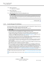
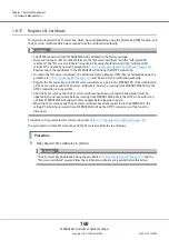
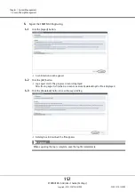
7

Click the [OK] button. 

 The registration of the SSL server key and SSL server certificate starts. 

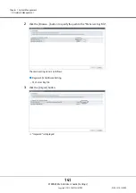
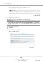
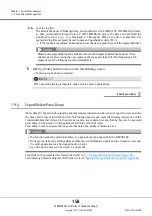
8

Click the [Done] button to return to the [Network] screen. 

End of procedure

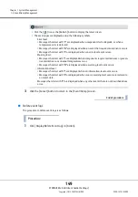
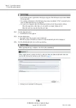
If an error screen appears under the following conditions, check the parameter settings.

When the imported file was not the "SSL server key file"

When the imported file was not the "SSL server certificate file"

When the imported "SSL server certificate file" was not the certificate which corresponds to the SSL 
server key

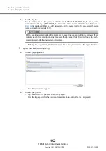
After registering the SSL server key or SSL server certificate, the information must be updated in the 
ETERNUS DX before being accessed from ETERNUS Web GUI via the HTTPS connection. Log out from 
ETERNUS Web GUI and wait a few minutes before logging in again. 

Summary of Contents for Eternus DX200F

Page 1: ...NUS Web GUI User s Guide Settings P2X0 1270 13ENZ0 FUJITSU Storage ETERNUS DX60 S3 DX100 S3 DX200 S3 ETERNUS DX500 S3 DX600 S3 ETERNUS DX8700 S3 DX8900 S3 Disk storage systems ETERNUS DX200F All Flash Array ...

Page 2: ...This page is intentionally left blank ...

Page 3: ...irmware versions V10L40 and later V10L25 and later when using the ETERNUS DX60 S3 V10L32 and later when using the ETERNUS DX100 S3 DX200 S3 the ETERNUS DX500 S3 DX600 S3 and the ETERNUS DX200F V10L33 and later when using ETERNUS DX storage systems in a Unified Storage environment Some of the functions herein may not be supported for firmware versions V10L31 and earlier Thirteenth Edition July 2015...

Page 4: ...FUJITSU Storage ETERNUS DX60 S3 Disk storage system Design Guide Basic FUJITSU Storage ETERNUS DX60 S3 Disk storage system Configuration Guide Basic FUJITSU Storage ETERNUS DX60 S3 Disk storage system Operation Guide Basic FUJITSU Storage ETERNUS DX100 S3 DX200 S3 Disk storage system Overview FUJITSU Storage ETERNUS DX100 S3 DX200 S3 Disk storage system Site Planning Guide FUJITSU Storage ETERNUS ...

Page 5: ... s Guide Operation FUJITSU Storage ETERNUS DX60 S3 DX100 S3 DX200 S3 ETERNUS DX500 S3 DX600 S3 ETERNUS DX8700 S3 DX8900 S3 Disk storage systems ETERNUS DX200F All Flash Array ETERNUS CLI User s Guide FUJITSU Storage ETERNUS DX60 S3 DX100 S3 DX200 S3 ETERNUS DX500 S3 DX600 S3 ETERNUS DX8700 S3 DX8900 S3 Disk storage systems ETERNUS DX200F All Flash Array FUJITSU Storage ETERNUS SF KM V2 5 Overview ...

Page 6: ...ed companies Mozilla Firefox and the Mozilla and Firefox logos are trademarks or registered trademarks of the Mozilla Foundation in the United States and other countries Intel is a trademark of Intel Corporation in the U S and other countries BS2000 is a registered trademark of Fujitsu Technology Solutions Other company names product names and service names are registered trademarks or trademarks ...

Page 7: ...erver 2008 Microsoft Windows Server 2008 Enterprise Microsoft Windows Server 2008 Standard Microsoft Windows Server 2008 for Itanium Based Systems Microsoft Windows Server 2008 HPC Edition Microsoft Windows Server 2008 R2 Datacenter Windows Server 2008 R2 Microsoft Windows Server 2008 R2 Enterprise Microsoft Windows Server 2008 R2 Standard Microsoft Windows Server 2008 R2 for Itanium Based Systems...

Page 8: ...ERNUS DX60 S3 100 S3 DX200 S3 Disk storage system ETERNUS DX60 S3 DX100 S3 DX200 S3 ETERNUS DX100 S3 DX200 S3 Disk storage system ETERNUS DX100 S3 DX200 S3 ETERNUS DX500 S3 DX600 S3 Disk storage system ETERNUS DX500 S3 DX600 S3 ETERNUS DX8700 S3 DX8900 S3 Disk storage system ETERNUS DX8700 S3 DX8900 S3 ETERNUS DX60 S3 Disk storage system ETERNUS DX60 S3 ETERNUS DX100 S3 Disk storage system ETERNUS...

Page 9: ...ms descriptions input conditions and display contents in operat ing procedures are described in the Parameter List Refer to Appendix A Parameter List page 665 Note that the screen shots in this manual were captured during development of the software and the actual screens may be different Microsoft product screen shot s reprinted with permission from Microsoft Corporation ...

Page 10: ... of packets can be reduced Note the following points when setting the transfer rate Set the same transfer rate for each network When the transfer rate for the ETERNUS DX is not Auto negotiation the same transfer rate must also be set for the network switches Do not use the standard buttons of each browser for example the Back button the Forward button and the Refresh button the F5 refresh key or t...

Page 11: ...under the Internet Options Security tab and disable Use SmartScreen Filter Set the following items for Compatibility View Settings under the Tools menu If an address for the ETERNUS DX is displayed in the Websites you ve added to Compatibility View field select and then delete the address Clear the Display intranet sites in Compatibility View checkbox Clear the Display all websites in Compatibilit...

Page 12: ...tup Power Management 48 1 4 9 Setup Extreme Cache 50 1 4 10 Setup Exclusive Read Cache 59 1 4 11 Setup Disk Drive Patrol 61 1 4 12 Setup Debug Mode 62 1 5 Utility Management 64 1 5 1 Shutdown Restart Storage System 64 1 5 2 Backup Configuration 66 1 5 3 Export Configuration 68 1 5 4 Start Stop Performance Monitoring 69 1 5 5 Clear Cache 71 1 6 Eco mode Management 75 1 6 1 Modify Eco mode General S...

Page 13: ...p Syslog 132 1 8 14 Setup SSH Server Key 134 1 8 15 Create Self signed SSL Certificate 135 1 8 16 Create Key CSR 137 1 8 17 Register SSL Certificate 140 1 9 Event Dump Management 144 1 9 1 Setup Event Notification 144 1 9 2 Display Delete Event Log 148 1 9 3 Export Delete Log 150 1 9 4 Export Delete Panic Dump 158 1 10 Audit Log Management 162 1 10 1 Enable Audit Log 162 1 10 2 Disable Audit Log 1...

Page 14: ...eters 201 1 13 6 Stop Restart Remote Support 204 1 14 Remote Support Management AIS Connect 206 1 14 1 Setup AIS Connect Environment 206 1 14 2 Setup Remote Session Permission 209 1 14 3 Send Log 210 1 14 4 Test Server Connectivity 211 1 14 5 Send AIS Connect Test Event 212 1 14 6 Import Root Certificate 213 1 15 Firmware Management 215 1 15 1 Apply Controller Firmware 215 1 15 2 Delete Controller...

Page 15: ...288 3 7 3 Optimize TPV FTV Capacity 289 3 7 4 Cancel Optimizing TPV FTV Capacity 290 3 7 5 Start Balancing Thin Provisioning Volume 291 3 7 6 Stop Balancing Thin Provisioning Volume 293 3 7 7 Reconfigure NAS Volume 294 3 7 8 Set Allocation 295 3 8 SDV SDPV Management 298 3 8 1 Delete Snap Data Pool Volume 298 3 8 2 Force Delete Snap Data Pool Volume 299 3 8 3 Initialize Snap Data Volume 300 3 9 St...

Page 16: ...odify Host Group 385 4 2 6 Modify Host Group FC FCoE 386 4 2 7 Modify Host Group iSCSI 391 4 2 8 Modify Host Group SAS 399 4 2 9 Add FC FCoE Host 405 4 2 10 Add iSCSI Host 410 4 2 11 Add SAS Host 416 4 2 12 Delete FC FCoE Host 420 4 2 13 Delete iSCSI Host 421 4 2 14 Delete SAS Host 422 4 2 15 Modify FC FCoE Host 423 4 2 16 Modify iSCSI Host 425 4 2 17 Modify SAS Host 427 4 3 CA Port Group Manageme...

Page 17: ...itoring 486 4 7 6 Stop Host LU QoS Performance Monitoring 487 4 7 7 Set FC FCoE Host QoS 489 4 7 8 Set iSCSI Host QoS 490 4 7 9 Set SAS Host QoS 492 4 7 10 Set FC Port QoS 493 4 7 11 Set iSCSI Port QoS 495 4 7 12 Set SAS Port QoS 496 4 7 13 Set FCoE Port QoS 498 4 7 14 Add LU QoS Group 499 4 7 15 Delete LU QoS Group 500 4 7 16 Modify LU QoS Group 501 4 8 NAS Management 503 4 8 1 Create Shared Fold...

Page 18: ...visioning 557 6 2 Create Thin Provisioning Pool 559 6 3 Delete Thin Provisioning Pool 568 6 4 Rename Thin Provisioning Pool 569 6 5 Expand Thin Provisioning Pool 571 6 6 Format Thin Provisioning Pool All Area 577 6 7 Format Thin Provisioning Pool Unformatted Area 579 6 8 Modify Threshold Thin Provisioning Pool 580 6 9 Modify Cache Parameters Thin Provisioning Pool 582 6 10 Assign Eco mode Schedule...

Page 19: ...k Buffer 655 7 8 11 Modify REC Multiplicity 656 7 8 12 Set REC Bandwidth Limit 658 7 9 ODX Management 660 7 9 1 Enable ODX 660 7 9 2 Disable ODX 661 7 9 3 Create ODX Buffer Volume 662 Appendix A Parameter List 665 A 1 System Management 665 A 1 1 Change User Password 666 A 1 2 Set SSH Public Key 666 A 1 3 System Settings 667 A 1 4 Utility Management 690 A 1 5 Eco mode Management 692 A 1 6 User Mana...

Page 20: ...ort Group Management 839 A 4 4 LUN Group Management 868 A 4 5 Host Response Management 870 A 4 6 Host LU QoS Management 878 A 4 7 NAS Management 883 A 5 RAID Group Management 903 A 5 1 Create RAID Group 903 A 5 2 Rename RAID Group 914 A 5 3 Change Controlling CM 915 A 5 4 Expand RAID Group 915 A 5 5 Modify RAID Group Parameters 917 A 5 6 Assign Eco mode Schedule RAID Group 920 A 5 7 Set Key Group ...

Page 21: ...ultiplicity 964 A 7 10 Set REC Bandwidth Limit 965 A 7 11 Create ODX Buffer Volume 966 Appendix B Factory Default List 970 B 1 System Management 970 B 2 Volume Management 988 B 3 Connectivity Management 992 B 4 RAID Group Management 1004 B 5 Thin Provisioning Management 1006 B 6 Advanced Copy Management 1009 Appendix C User Roles and Policies 1014 C 1 Roles 1014 C 2 Availability of Functions for e...

Page 22: ... is Tuned For WSV Type Volumes 1062 F 1 5 Basic Size When Stripe Depth is Tuned For TPP Capacity 1065 F 2 Input Conditions for MWC 1066 F 2 1 Allowed Input for MWC When Using the Default Stripe Depth Value 1066 F 2 2 Allowed Input for MWC When the Stripe Depth Value is Tuned 1068 Appendix G Using RADIUS Authentication 1070 G 1 Using RADIUS Authentication to Access the ETERNUS DX 1070 G 2 Notes whe...

Page 23: ...ETERNUS Web GUI User s Guide Settings Copyright 2015 FUJITSU LIMITED P2X0 1270 13ENZ0 23 List of Figures Figure F 1 Basic size when creating volumes 1056 ...

Page 24: ...ion Change User Password System Basic Information Set SSH Public Key System Basic Information System Settings Modify Storage System Name System Settings Modify Date and Time Change Box ID Setup Subsystem Parameters Setup Encryption Mode Setup SMI S Environment Register SED Authentication Key Setup Power Management Setup Extreme Cache Setup Exclusive Read Cache Setup Disk Drive Patrol Setup Debug M...

Page 25: ...etup SNMP Agent MIB Access View Setup SNMP Agent User Setup SNMP Agent Community Setup SNMP Agent Trap Download MIB File Send SNMP Trap Test Display SMTP Log Setup E Mail Notification Setup Syslog Setup SSH Server Key Create Self signed SSL Certificate Create Key CSR Register SSL Certificate Event Dump Management Setup Event Notification Event Dump Display Delete Event Log Export Delete Log Export...

Page 26: ...lt Path Group Information Detail screen Restart Storage Migration Suspend Storage Migration Stop Storage Migration Remote Support Management REMCS Display Communication Log Remote Support Management REMCS Setup Remote Support Update Customer Information Update Communication Environment Information Setup Log Sending Parameters Stop Restart Remote Support Remote Support Management AIS Connect Setup ...

Page 27: ...unctions 1 Set Storage System Name 2 Change User Password 3 Set Thin Provisioning 4 Register Advanced Copy License 5 Register SED Authentication Key 6 Set Network Environment Initial Setup 2 Makes the reporting settings for when an error occurs in the ETERNUS DX The settings can be omitted if the reporting function will not be used Refer to Initial Setup 2 in FUJITSU Storage ETERNUS DX Configurati...

Page 28: ...ssword is as follows Procedure 1 Click Change User Password in Action 2 Specify the parameters The main setting items are as follows Password Setting Old Password New Password Confirm New Password When RADIUS Authentication is used for login the password cannot be changed If an error screen appears under the following conditions check the parameter settings Each parameter is not entered Each param...

Page 29: ...b GUI User s Guide Settings Copyright 2015 FUJITSU LIMITED P2X0 1270 13ENZ0 29 3 Click the Change button A confirmation screen appears 4 Click the OK button Changing of the user password starts 5 Click the Done button to return to the System screen End of procedure ...

Page 30: ...ecify the SSH Public Key The main setting item is as follows SSH Public Key Setting SSH Public Key When using the SSH Client Key authentication create a pair of the SSH client public key and the SSH client secret key in advance using the creation tool One public key can be registered per user account When this function is executed the public key is registered in the ETERNUS DX The following types ...

Page 31: ...I User s Guide Settings Copyright 2015 FUJITSU LIMITED P2X0 1270 13ENZ0 31 3 Click the Set button A confirmation screen appears 4 Click the OK button The registration of the SSH public key starts 5 Click the Done button to return to the System screen End of procedure ...

Page 32: ... Setup Disk Drive Patrol Setup Debug Mode 1 4 1 Modify Storage System Name This function registers the name administrator and the installation site of the ETERNUS DX Information registered in this screen is used for the following functions and screens Network management using Simple Network Management Protocol SNMP Storage system name displayed in the login screen and the operation screens For det...

Page 33: ...age System Name Installation Location Administrator Description 3 Click the Set button A confirmation screen appears 4 Click the OK button Setting of the storage system name starts 5 Click the Done button to return to the System Settings screen End of procedure If an error screen appears under the following conditions check the parameter settings The Name is not entered A parameter does not satisf...

Page 34: ... to A 1 3 2 Modify Date and Time page 667 For the factory default settings for this function refer to Appendix B Modify Date and Time page 972 The procedure to set the date and time is as follows Procedure 1 Click Modify Date and Time in Action When the network environment is set to the factory default the NTP function cannot be used To perform the network environment settings refer to 1 8 1 Setup...

Page 35: ...UJITSU LIMITED P2X0 1270 13ENZ0 35 2 Specify the parameters The main setting items are as follows Date Time Information Date Time Zone Settings Time Zone Time Zone time difference setting Daylight Saving Time Settings Set Range By day of the week Range By Date NTP Settings NTP server LAN Port used for NTP ...

Page 36: ... secondary NTP server Yes is selected for Synchronize with NTP Server the LAN port that is used for the NTP server is MNT and the IPv4 address of the NTP server and the broadcast address of the MNT port are the same Yes is selected for Synchronize with NTP Server the LAN port that is used for the NTP server is RMT and the IPv4 address of the NTP server and the broadcast address of the RMT port are...

Page 37: ...lt settings for this function refer to Appendix B Change Box ID page 972 If Yes is selected for Synchronize with NTP Server when there is no NTP server connection or when communication with the NTP server is unstable the required time for the date and time setting may take longer Wait until the screen is updated Even if connection to the NTP server fails the date and time setting appear as though ...

Page 38: ...rmation screen appears 4 Click the OK button The specified Box ID is registered 5 Click the Done button to return to the System Settings screen End of procedure If an error screen appears under the following conditions check the parameter settings A Box ID is not input The entered value of a Box ID contains a character other than alphabetic characters upper case numeric characters hash key charact...

Page 39: ...etup Subsystem Parameters page 672 For the factory default settings for this function refer to Appendix B Setup Subsystem Parameters page 973 The procedure to set the subsystem parameters is as follows Procedure 1 Click Setup Subsystem Parameters in Action If a change to subsystem parameters is required the recommended time is when the load is low in the ETERNUS DX Some subsystem parameters may re...

Page 40: ...follows Setup Subsystem Parameters Thin Provisioning Allocation Mode Setup Host Load Balance Reject INQUIRY from Unauthorized Host Setup Disk Drive Copybackless Web GUI Settings Function to Add Host 3 Click the Set button A confirmation screen appears 4 Click the OK button Setting of the subsystem parameter starts 5 Click the Done button to return to the System Settings screen End of procedure ...

Page 41: ...en disabling the encryption mode reboot the ETERNUS DX When changing the encryption mode delete all the encrypted volumes and volumes being encrypted in advance Once a volume has been encrypted it cannot be changed back to a non encrypted volume This function cannot be changed in the following conditions Encrypted volumes exist Volumes being encrypted exist When using the encryption function in a ...

Page 42: ...Setup Encryption Mode Encryption Mode 3 Click the Set button A confirmation screen appears 4 Click the OK button The encryption mode setting is performed 5 Click the Done button to return to the System Settings screen End of procedure If the Set button is clicked when encrypted volumes or volumes being encrypted exist an error screen is displayed When disabling the encryption mode reboot the ETERN...

Page 43: ...ings for this function refer to Appendix B Setup SMI S Environment page 973 The procedure to enable or disable the SMI S function is as follows Enabling or disabling the SMI S function when the controller firmware version is V10L2x or earlier ETERNUS DX60 S3 Procedure 1 Click Setup SMI S Environment in Action When switching the SMI S setting between enabled or disabled reboot the ETERNUS DX for th...

Page 44: ... parameters The main setting item is as follows Set SMI S SMI S Select whether to Enable or Disable the SMI S function 3 Click the Set button A confirmation screen appears 4 Click the OK button The SMI S setting is performed 5 Click the Done button to return to the System Settings screen End of procedure Reboot the ETERNUS DX to apply the new setting ...

Page 45: ...5 Enabling the SMI S when the controller firmware version is V10L30 or later other than the ETERNUS DX60 S3 Procedure 1 Click Setup SMI S Environment in Action 2 Click the Start button A confirmation screen appears 3 Click the OK button SMI S setting starts 4 Click the Done button to return to the System Settings screen End of procedure ...

Page 46: ...46 Disabling the SMI S when the controller firmware version is V10L30 or later other than the ETERNUS DX60 S3 Procedure 1 Click Setup SMI S Environment in Action 2 Click the Stop button A confirmation screen appears 3 Click the OK button SMI S setting stops 4 Click the Done button to return to the System Settings screen End of procedure ...

Page 47: ...thentication key registration starts The ETERNUS DX60 S3 does not support this function Register the SED authentication key before installing SEDs in the ETERNUS DX If a SED is installed without registering the SED authentication key data leakage in a SED that is removed may occur If a SED is installed before registering the SED authentication key register the SED authentication key and reboot the...

Page 48: ... DX power For details on the parameters for this function refer to A 1 3 7 Setup Power Management page 678 For the factory default settings for this function refer to Appendix B Setup Power Management page 974 The procedure to perform power management setting is as follows Procedure 1 Click Setup Power Management in Action 2 Specify the parameters For the ETERNUS DX8700 S3 DX8900 S3 If this functi...

Page 49: ... PWC Connection Settings Connection CM for ETERNUS DX models other than the ETERNUS DX8700 S3 DX8900 S3 Connection SVC for the ETERNUS DX8700 S3 DX8900 S3 Delay until Shutdown Set management unit interface Power Failure Signal Low Battery Signal UPS Shutdown Signal 3 Click the Set button A confirmation screen appears 4 Click the OK button Setting of the power management starts 5 Click the Done but...

Page 50: ...e system status is Not Ready Pinned data exists in the ETERNUS DX A CM that is not in Normal status exists A PFM that is not in Normal or Warning status exists when Extreme Cache is selected If an EXCP includes a RAID group without an Available status the setting values and set state of the tuning parameter cannot be changed When Extreme Cache Pool is selected Note the following points The cache t...

Page 51: ... DX8900 S3 installing the same number of PFMs for each CM is not required By clicking the Set button the PFM capacity that is installed in each CM is set as the available EXC memory size When the performance monitoring process is started the current PFM busy rate can be checked Refer to Performance PCIe Flash Module in ETERNUS Web GUI User s Guide Operation for details To enable or disable EXC for...

Page 52: ...ht 2015 FUJITSU LIMITED P2X0 1270 13ENZ0 52 2 Select Extreme Cache for Cache Used and input the detailed information For the ETERNUS DX8700 S3 DX8900 S3 For the other models The main setting items are as follows Extreme Cache Memory Size Settings New Memory Size for the ETERNUS DX500 S3 DX600 S3 ...

Page 53: ...t after removing the PFM the Current Size or EXC memory size of all the CMs is changed to 0 GB To use EXC use this function to set the EXC memory size Removing the PFM must be performed by a maintenance engineer with a user account that has the Maintenance Operation policy If an error screen appears for the ETERNUS DX500 S3 DX600 S3 under the following conditions check the parameter settings The N...

Page 54: ...creating RAID groups are listed below Select drives with the same capacity If drives of different capacities exist in a RAID group the smallest capacity becomes the standard and all other drives are regarded as having the same capacity as the smallest drive In this case the remaining drive space is not used Select SSDs with the same type SSD M SSD If different types of SSDs exist in a RAID group t...

Page 55: ...ent 1 4 System Management ETERNUS Web GUI User s Guide Settings Copyright 2015 FUJITSU LIMITED P2X0 1270 13ENZ0 55 For the other models 3 Click the Memory Size link for the CM to set an EXCP For the ETERNUS DX8700 S3 DX8900 S3 ...

Page 56: ...he Tabular tab to select SSDs from the list For the ETERNUS DX8700 S3 DX8900 S3 only unused SSDs in the DE that is connected to the CE with the CM where the EXCP memory size is to be set are displayed For the other models unused SSDs in the ETERNUS DX are displayed The main setting items are as follows Checkbox to select drives When SSD Ms with an interface speed of 12Gbit s are installed in a hig...

Page 57: ...ive installation image The installation images of all the drives installed in the ETERNUS DX are displayed Checkboxes are displayed for unused SSDs For the ETERNUS DX8700 S3 DX8900 S3 For the other models The main setting items are as follows DE selection list box Checkbox to select drives 5 Click the OK button Returns to the Extreme Cache Settings screen 6 To set EXCP memory sizes in multiple CMs...

Page 58: ...Management ETERNUS Web GUI User s Guide Settings Copyright 2015 FUJITSU LIMITED P2X0 1270 13ENZ0 58 7 Check the EXCP memory size and click the Set button For the ETERNUS DX8700 S3 DX8900 S3 For the other models A confirmation screen appears ...

Page 59: ... in the Memory Size field 0GB is displayed when no SSD is selected When the maximum number of SSDs has already been selected a hyphen is displayed The number of selectable SSDs is described below ETERNUS DX100 S3 DX200 S3 1 0GB 400GB ETERNUS DX500 S3 DX600 S3 1 4 0GB 400GB 800GB 1200GB 1600GB ETERNUS DX8700 S3 DX8900 S3 1 4 0GB 400GB 800GB 1200GB 1600GB Refer to Available EXCP memory size page 684...

Page 60: ...cache is as follows Procedure 1 Click Setup Exclusive Read Cache in Action 2 Select the exclusive read cache The main setting item is as follows Cache Size Settings Exclusive Read Cache 3 Click the Set button A confirmation screen appears 4 Click the OK button The exclusive read cache setting starts 5 Click the Done button to return to the System Settings screen End of procedure ...

Page 61: ... to enable or disable the disk patrol function is as follows Procedure 1 Click Setup Disk Patrol in Action 2 Specify whether to enable or disable the disk patrol function This function is performed without any relation to Host I O This function is effective for diagnosing the state of drives and hot spares that are not often used Set this function to detect any drive failures at an early stage Whe...

Page 62: ...storage system information and the collection mode for panic dumps when errors occur For details on the parameters for this function refer to A 1 3 11 Setup Debug Mode page 689 For the factory default settings for this function refer to Appendix B Setup Debug Mode page 975 The procedure to set the collection conditions for the storage system information is as follows Procedure 1 Click Setup Debug ...

Page 63: ... s Guide Settings Copyright 2015 FUJITSU LIMITED P2X0 1270 13ENZ0 63 2 Specify the parameters 3 Click the Set button A confirmation screen appears 4 Click the OK button The debug mode is set 5 Click the Done button to return to the System Settings screen End of procedure ...

Page 64: ...down or restart on the screen Shutdown the ETERNUS DX The procedure to shut down the ETERNUS DX is as follows Procedure 1 Click Shutdown Restart in Action This function can be used regardless of whether the Setup Power Management is enabled or disabled Note that the ETERNUS DX may reboot automatically when Setup Power Management is enabled For example an ETERNUS DX that is turned off reboots when ...

Page 65: ...ick the Shutdown button A confirmation screen appears 3 Click the OK button The ETERNUS DX shuts down after 30 seconds End of procedure Restart the ETERNUS DX The procedure to restart the ETERNUS DX is as follows Procedure 1 Click Shutdown Restart in Action Note that the ETERNUS DX may reboot automatically when Setup Power Management is enabled ...

Page 66: ...s of configuration definition data can be stored For details on the parameters for this function refer to A 1 4 1 Backup Configuration page 690 For the factory default settings for this function refer to Appendix B Backup Configuration page 975 The procedure to backup configuration definition file is as follows Procedure 1 Click Backup Configuration in Action This function cannot be used under the...

Page 67: ...rs The main setting items are as follows Select Configuration Definition Configuration Definition Data Note text box Select Backup Slot Configuration Definition Data 3 Click the Backup button A confirmation screen appears 4 Click the OK button The configuration definition data is backed up 5 Click the Done button to return to the Utility screen End of procedure ...

Page 68: ... file to be saved must be cfg The default file name is Conf_serial number for the ETERNUS DX_YYYY MM DD_hh mm ss cfg YYYY MM DD_hh mm ss the date and time when the download screen Step 2 is displayed The configuration information is exported The obtained configuration files may be required to restore the ETERNUS DX if an error occurs When altering the ETERNUS DX configuration information it is rec...

Page 69: ...s function refer to Appendix B Start Stop Performance Monitoring page 975 The procedure to start or stop performance monitoring is as follows Starting performance monitoring The Start button is displayed when the Monitoring State is Stopped Procedure 1 Click Start Stop Perfmon in Action When exporting of the configuration information has been completed save the log immediately When the ETERNUS DX ...

Page 70: ...tart button A confirmation screen appears 4 Click the OK button Acquisition of performance information starts 5 Click the Done button to return to the Utility screen End of procedure Stopping performance monitoring The Stop button is displayed when Monitoring State is Active Procedure 1 Click Start Stop Perfmon in Action If the Stop button is clicked after starting performance monitoring from othe...

Page 71: ... return to the Utility screen End of procedure 1 5 5 Clear Cache This function clears all of the data on the CM cache memory data on the EXC and data on the EXCP hereinafter collectively referred to as cache data This function is used when monitoring the system performance Cache data to be cleared Read data on the CM EXC 1 and EXCP 1 Multiple cache data to be cleared can be selected from CM EXC 1 ...

Page 72: ...ED turns off execute this function Perform the Force Write Back function to write the Dirty data back to the drive and then execute this function Note that the Force Write Back function can be performed by a maintenance engineer who has the Maintenance Operation policy This function cannot be used under the following conditions The storage system status is Not Ready The CM status is not Normal The...

Page 73: ...s Target Cache 3 Click the Clear button A confirmation screen appears When Extreme Cache or Extreme Cache Pool is selected and the clear conditions are not satisfied an error occurs Check the parameter settings If an error screen appears under the following conditions check the parameter settings The system or CM status is not normal The PFM status is not normal when selecting Extreme Cache The st...

Page 74: ... 5 Utility Management ETERNUS Web GUI User s Guide Settings Copyright 2015 FUJITSU LIMITED P2X0 1270 13ENZ0 74 4 Click the OK button The cache data is cleared 5 Click the Done button to return to the Utility screen End of procedure ...

Page 75: ...al Setting page 692 For the factory default settings for this function refer to Appendix B Modify Eco mode General Setting page 976 The procedure to set the Eco mode schedule for a RAID group is as follows Procedure 1 Click Modify Eco mode Setting in Action The ETERNUS DX200F does not support Eco mode management functions Eco mode is not available for the following drives Hot Spares except Dedicat...

Page 76: ...A confirmation screen appears 4 Click the OK button The application of the Eco mode general settings starts 5 Click the Done button to return to the Eco mode screen End of procedure 1 6 2 Create Eco mode Schedule This function specifies the disk operating time term for activating disk motor constantly as an Eco mode schedule Up to 64 Eco mode schedules can be created for each storage system Up to ...

Page 77: ...RNUS DX S3 series must be enabled Disk operation time varies depending on the Eco mode schedule settings and disk access A disk is spun up even if it is outside of disk operation time in the following conditions If disk access occurs while the disk motor is stopped The disk is immediately spun up and can be accessed within 1 5 minutes If a disk is activated more than a set amount of times in a day...

Page 78: ...he same and the start time is later than the end time Specific days is selected for the event type and a non existent date for example February 30 is set Specific days is selected for the event type when One day only is selected for the period and the start time and end time are the same Specific days is selected for the event type when One day only is selected for the period and the start time is...

Page 79: ...e Set button A confirmation screen appears 7 Click the OK button Creation of the Eco mode schedule starts 8 Click the Done button to return to the Eco mode screen End of procedure When deleting the added event select the event and click the Delete button When changing the added event select the event and click the Edit button If an error screen appears under the following conditions check the para...

Page 80: ... 6 4 Modify Eco mode Schedule This function modifies the Eco mode schedule Up to eight events can be specified for a single Eco mode schedule An Eco mode schedule that is allocated to a RAID group cannot be deleted An Eco mode schedule that is allocated to a Thin Provisioning Pool cannot be deleted Disk operation time varies depending on the Eco mode schedule settings and disk access A disk is spu...

Page 81: ...lows Procedure 1 Select the Eco mode schedule that is to be edited and click Modify Schedule in Action 2 Select the event that is to be modified and click the Edit Event button 3 Modify the event content To apply the modified Eco mode schedule to each RAID group refer to the procedure in 5 7 Assign Eco mode Schedule RAID Group page 547 To apply the modified Eco mode schedule to each Thin Provision...

Page 82: ...e end time Specific days is selected for the event type and a non existent date for example February 30 is set Specific days is selected for the event type when One day only is selected for the period and the start time and end time are the same Specific days is selected for the event type when One day only is selected for the period and the start time is later than the end time Specific week is s...

Page 83: ...nts click the Set button A confirmation screen appears 7 Click the OK button Modification of the Eco mode schedule starts 8 Click the Done button to return to the Eco mode screen End of procedure If an error screen appears under the following conditions check the parameter settings Schedule Name has not been entered Schedule Name matches with an existing schedule name ...

Page 84: ...n the ETERNUS DX The following types formats of public keys can be used IETF style DSA for SSH v2 IETF style RSA for SSH v2 The supported maximum encryption strength for the public key is 4096 bit User ID for user accounts cannot be changed Changed or deleted user accounts become available at the next login The last user account with administrator privileges role of Admin added cannot be deleted F...

Page 85: ...TERNUS Web GUI User s Guide Settings Copyright 2015 FUJITSU LIMITED P2X0 1270 13ENZ0 85 Add User Account The procedure to add a user accounts is as follows Procedure 1 Click Setup User Account in Action 2 Click the Add button 3 Specify the parameters ...

Page 86: ... return to the Define Role screen End of procedure Edit User Account The procedure to edit a user accounts is as follows Procedure 1 Click Setup User Account in Action Software is the dedicated role that is used for external software A user account with the Software role cannot log in to ETERNUS Web GUI If an error screen appears under the following conditions check the parameter settings When a p...

Page 87: ... P2X0 1270 13ENZ0 87 2 Select the user account to be modified The main setting item is as follows Registered User Account List Checkbox 3 Click the Edit button 4 Change the parameters The main setting items are as follows Edit User Account Change Password New Password Confirm New Password Role Account SSH Public Key ...

Page 88: ...unt in Action 2 Select the deletion target user accounts multiple selections can be made Software is the dedicated role that is used for external software A user account with the Software role cannot log in to ETERNUS Web GUI To change the password select the Change Password checkbox If an error screen appears under the following conditions check the parameter settings When a parameter does not sa...

Page 89: ...the user accounts to the factory default status The procedure to initialize user accounts is as follows Procedure 1 Click Initialize User Account in Action The last user account with the administrator privileges cannot be deleted By using this function all the registered user accounts are deleted and only the factory default account remains The password for the default account is restored to the d...

Page 90: ...istered Enable or disable RADIUS Authentication for each storage system If RADIUS Authentication fails when No has been selected for Recovery Mode in the RADIUS Setting field logging in to ETERNUS Web GUI will not be available RADIUS Authentication cannot be used when logging in to the Slave CM When Yes Communication error has been selected for Recovery Mode in the RADIUS Setting field Internal Au...

Page 91: ... items are as follows RADIUS Setting RADIUS Authentication Recovery Mode Primary Server required Secondary Server Domain Name IP Address Port No LAN Port Authentication Mode Shared Secret Retry Out Time There are supplementary notes when using RADIUS Authentication Refer to Appendix G Using RADIUS Authentication page 1070 for details When using RADIUS Authentication registering user account inform...

Page 92: ...erver An error screen appears if the specified IP address of the RADIUS server conflicts with the internal IP address of the ETERNUS DX If this occurs check the parameter settings Policies Description Status Display Status display functions storage system status RAID group list volume list copy session list etc RAID Group Management RAID group Thin Provisioning Pool Eco mode hot spare disk setting...

Page 93: ...ting functions create change delete etc Security Setting Encryption setting functions of drives etc Maintenance Information Exporting and deleting functions of maintenance information performance information configuration information events storage system logs panic dumps etc Firmware Management Firmware management functions for users without the Maintenance Oper ation policy who need to set the c...

Page 94: ...ms are as follows Role Setting Name Target Policy Policies 3 Click the Create button A confirmation screen appears 4 Click the OK button Application of the role settings starts 5 Click the Done button to return to the Define Role screen End of procedure If an error screen appears under the following conditions check the parameter settings The Name does not satisfy the input conditions The Name has...

Page 95: ... The user role is deleted 3 Click the Done button to return to the Define Role screen End of procedure 1 7 6 Modify Role This function modifies the policies of the user specific role custom role The existing role default role cannot be deleted The user role which is allocated to a user account cannot be deleted Policies of the existing role default role cannot be changed Policies which have been g...

Page 96: ...d and click Modify Role in Action 2 Change the role settings The main setting item is as follows Target Role Policies 3 Click the Modify button A confirmation screen appears 4 Click the OK button Modification of the role settings starts 5 Click the Done button to return to the Define Role screen End of procedure Multiple policies can be allocated to one role The modified role can be granted to the...

Page 97: ...cation Setup Syslog Setup SSH Server Key Create Self signed SSL Certificate Create Key CSR Register SSL Certificate 1 8 1 Setup Network Environment This function sets up an the environment for the ETERNUS DX to communicate with an external network Configuration is required for each MNT RMT and FST port MNT port The MNT port is used for general communication between the ETERNUS DX and the external ...

Page 98: ...the network environment settings for the MNT port are incomplete Refer to Functions that cannot be performed in a factory default network environment page 98 for details When the network environment settings are the same as the factory default all the input items in the IPv4 Settings tab for the MNT port are cleared Information that is configured in the ETERNUS DX is not displayed Note that in the...

Page 99: ...ocedure to set network environment using IPv4 address is as follows Procedure 1 Select which port to set the network environment for and click Setup Network Environment in Action Model MNT port RMT port FST port Setting Modification Deletion Setting Modification Deletion Setting Modification Deletion ETERNUS DX60 S3 OK OK OK 1 OK OK OK 1 N A ETERNUS DX100 S3 OK OK OK 1 OK OK OK 1 N A ETERNUS DX200...

Page 100: ... 13ENZ0 100 2 Specify the parameters If the gateway is specified the information of the remote storage systems for which network access will be allowed can be input The main setting items are as follows LAN Speed and Duplex Wake on LAN Interface Master IP Address Slave IP Address Subnet Mask Gateway DNS Primary DNS Secondary DNS ...

Page 101: ... 101 3 To allow access from a different subnetwork to the ETERNUS DX click the Add button The Add Allowable IP Address screen appears 4 Input the IP address and the subnet mask The main setting items are as follows Allowable IP Address Settings IP Address Subnet Mask 5 Click the OK button Returns to the Setup Network Environment screen ...

Page 102: ...M Specify the IP address of Gateway when allowing access from outside of the subnetwork The IP address must be in the same subnetwork as the port For Allowable IP Address specify the IP address or the network address that allows access to the ETERNUS DX These settings are not required for access from the network address same subnetwork which the ETERNUS DX belongs to Click the Clear button to dele...

Page 103: ... follows Procedure 1 Select which port to set the network environment for and click Setup Network Environment in Action 2 Specify the parameters If the gateway is specified the information of the remote storage systems for which network access will be allowed can be input The main setting items are as follows LAN Speed and Duplex Wake on LAN Device management operation cannot be continued if the I...

Page 104: ...gth of Subnet Prefix Gateway DNS Primary DNS Secondary DNS 3 To allow access from a different subnetwork to the ETERNUS DX click the Add button The Add Allowable IP Address screen appears Click the Automatic discovery button to automatically obtain Master IP Link Local Address Master Connect IP Address Slave IP Link Local Address Slave Connect IP Address Length of Subnet Prefix and Gateway Input t...

Page 105: ...s Copyright 2015 FUJITSU LIMITED P2X0 1270 13ENZ0 105 4 Input Connect IP Address and Length of Subnet Prefix The main setting items are as follows Allowable IP Address Settings Connect IP Address Length of Subnet Prefix 5 Click the OK button Returns to the Setup Network Environment screen ...

Page 106: ...be in the same subnetwork as the Master CM Specify the IP address of Gateway when allowing access from outside of the subnetwork The IP address must be in the same subnetwork as the port For Allowable IP Address specify the IP address or the network address that allows access to the ETERNUS DX These settings are not required for access from the network address same subnetwork which the ETERNUS DX ...

Page 107: ...st 0 of a block that follows consecutive zeros 2 Replacement of 0000 blocks with 0 3 Replacement of a block with consecutive zeros by is performed only once Device management operation cannot be continued if the IP address of the ETERNUS DX has been changed Logging in again with the new IP address is required No Allocated addresses Settable range for addresses Length of subnet prefix 1 Global addr...

Page 108: ...v4 When accessing of the ETERNUS DX from a specific client outside the subnetwork is allowed specify IP Address and Subnet Mask IP Address 10 20 30 40 Subnet Mask 255 255 255 255 When accessing of the ETERNUS DX from a specific subnetwork outside the subnetwork is allowed specify Network Address and Subnet Mask IP Address 10 20 30 0 Subnet Mask 255 255 255 0 For IPv6 IP Address corresponds to Conn...

Page 109: ...nnection have been disabled ETERNUS CLI cannot access the ETERNUS DX If ports of all the services are disabled access to the ETERNUS DX is not allowed When the firewall setting is changed it takes approximately 10 seconds to update the storage system information To display the most recently updated screen wait at least 10 seconds and click the icon in the Network screen or click Network in the cat...

Page 110: ...B Setup Firewall page 980 The procedure to set a firewall is as follows Procedure 1 Select which port to set the firewall for multiple selections can be made and click Setup Firewall in Action 2 Specify whether to enable or disable the connection of each service The main setting items are as follows Firewall Settings HTTP HTTPS Telnet SSH ICMP Maintenance Secure SNMP RCIL ETERNUS DX Discovery 3 Cl...

Page 111: ...the procedure in 1 8 1 Setup Network Environment page 97 Before enabling the SNMP function use the procedure in 1 8 2 Setup Firewall page 109 to allow the SNMP for the setting target LAN port By using 1 1 Initial Setup page 27 the SNMP Agent environment can be configured with the wizard Refer to Initial Setup in FUJITSU Storage ETERNUS DX Configuration Guide Web GUI When the Initial Setup function...

Page 112: ...Interface in Action 2 Specify the parameters The main setting items are as follows Basic Interface SNMP Function LAN Port used for SNMP Authentication Failure 3 Click the Set button A confirmation screen appears 4 Click the OK button Setting of the SNMP Agent basic interface starts 5 Click the Done button to return to the Network screen End of procedure If the entered engine ID does not satisfy th...

Page 113: ...P Manager page 980 The procedure to set the SNMP Manager is as follows Procedure 1 Click Setup SNMP Manager in Action 2 When adding a Manager IP address click the Add button Click the Manager link to edit the Manager IP address The Manager screen appears If the SNMP Function is disabled this function cannot be used The IP address of the SNMP Manager that is used in the settings in 1 8 7 Setup SNMP...

Page 114: ...the Manager IP address The main setting items are as follows Manager IP Version Manager IP Address IPv4 Manager IP Address IPv6 4 Click the OK button Returns to the original screen 5 Repeat Step 2 through Step 4 when registering several Manager IP addresses 6 After adding or editing the Manager IP address click the Set button A confirmation screen appears ...

Page 115: ...he default view can be created for each ETERNUS DX There are three types of default views ViewALL View mib2 and View exmib For details on the parameters for this function refer to A 1 7 5 Setup SNMP Agent MIB Access View page 712 For the factory default settings for this function refer to Appendix B Setup SNMP Agent MIB Access View page 981 The procedure to change the SNMP Agent MIB view is as fol...

Page 116: ...0 13ENZ0 116 2 When adding an MIB View click the Add button Click the View Name link to edit the MIB View The MIB Access View screen appears 3 Add or edit the MIB View The main setting items are as follows MIB Access View View Name Subtree1 Subtree10 To delete the existing MIB View click the Delete button for the target MIB View ...

Page 117: ...SNMP Agent User This function sets up the user which accesses the SNMP Agent The security level and the MIB access range are configured for each user Up to ten users can be specified for each ETERNUS DX If the SNMP Function is disabled the Setup SNMP Manager function cannot be used The user name that is used in the settings in 1 8 8 Setup SNMP Agent Trap page 123 cannot be changed or deleted Howev...

Page 118: ...tion refer to Appendix B Setup SNMP Agent User page 981 The procedure to set the user to access the SNMP Agent is as follows Procedure 1 Click Setup SNMP User in Action 2 When adding a user click the Add button Click the User Name link to edit the user The Setup SNMP Agent User screen appears The authentication and encryption can be enabled disabled and also the MIB access range can be specified f...

Page 119: ...The main setting items are as follows Setup SNMP Agent User User Name MIB View Setting Authentication Authentication Method Authentication Password Retype Authentication Password Encryption Encryption Method Encryption Password Retype Encryption Password 4 Click the OK button Returns to the original screen 5 Repeat Step 2 through Step 4 to configure several users ...

Page 120: ...ord for SNMP Manager to access the SNMP Agent of the ETERNUS DX The SNMP Agent only accepts a request from SNMP Manager if the specified community names for SNMP Manager and SNMP Agent are the same Up to ten communities can be specified for each ETERNUS DX If the SNMP Function is disabled the Setup SNMP Manager function cannot be used The community name that is used in the settings in 1 8 8 Setup ...

Page 121: ... For the factory default settings for this function refer to Appendix B Setup SNMP Agent Community page 981 The procedure to set the SNMP Agent community is as follows Procedure 1 Click Setup SNMP Community in Action 2 When adding a community click the Add button Click the Community Name link to edit the community The Setup SNMP Agent Community screen appears To delete the existing community click...

Page 122: ...d or edit the community The main setting items are as follows Setup SNMP Agent Community Community Name View Name Allowed SNMP Manager List 4 Click the OK button Returns to the original screen 5 Repeat Step 2 through Step 4 to configure several communities 6 After adding or editing the community click the Set button A confirmation screen appears ...

Page 123: ...c Up to ten traps can be specified for each ETERNUS DX For details on the parameters for this function refer to A 1 7 8 Setup SNMP Agent Trap page 716 For the factory default settings for this function refer to Appendix B Setup SNMP Agent Trap page 981 The procedure to set the SNMP Agent trap is as follows Procedure 1 Click Setup SNMP Trap in Action If the SNMP Function is disabled the Setup SNMP ...

Page 124: ...When adding a trap click the Add button Click the Trap No link to edit the trap The Setup SNMP Agent Trap screen appears 3 Add or edit the trap information The main setting items are as follows Setup SNMP Agent Trap Manager No SNMP Version Community Name User Name Port No To delete the existing trap click the Delete button for the target trap ...

Page 125: ...g traps click the Set button A confirmation screen appears 7 Click the OK button Setting of the SNMP Agent Trap starts 8 Click the Done button to return to the Network screen End of procedure If an error screen appears under the following conditions check the parameter settings When Manager No or Community Name User Name is not input When a trap with the same parameters except the Trap No exists W...

Page 126: ... is used by the application which uses SNMP SNMP Manager For details on the parameters for this function refer to A 1 7 9 Download MIB File page 717 For the factory default settings for this function refer to Appendix B Download MIB File page 981 The procedure to download an MIB file as follows Procedure 1 Click Download MIB File in Action 2 Specify the parameters The main setting items are as fol...

Page 127: ... from the SNMP Agent to the SNMP Manager The SNMP Trap is the event information reported by the ETERNUS DX SNMP Agent Perform SNMP Agent and SNMP Manager settings before executing this test Perform the following settings before executing this test If the SNMP function is disabled the trap test cannot be performed Setup Network Environment Setup SNMP Agent Basic Interface Setup SNMP Manager Setup S...

Page 128: ...the SNMP Trap test is as follows Procedure 1 Click Send SNMP Trap in Action Click the Send button A confirmation screen appears 2 Click the OK button The SNMP Trap test is performed 3 Click the Done button to return to the Network screen End of procedure Confirm that the trap has been successfully received by SNMP Manager after the SNMP Trap test has been performed ...

Page 129: ...contains requests from the ETERNUS DX to the server and responses from the server to the ETERNUS DX Only the E Mail communication log for the last executed event is displayed The procedure to display SMTP log is as follows Procedure 1 Click Display SMTP Log in Action 2 Check the displayed Event Type and the Communication Log 3 Click the Cancel button to return to the Network screen End of procedur...

Page 130: ...details on the parameters for this function refer to A 1 7 10 Setup E Mail Notification page 717 For the factory default settings for this function refer to Appendix B Setup E Mail Notification page 982 The procedure to set a E Mail notification is as follows Procedure 1 Click Setup E Mail Notification in Action 2 Specify the parameters When stopping the event notification via E Mail perform one o...

Page 131: ...n Method User Name Password 3 Click the Set button A confirmation screen appears 4 Click the OK button The specified E mail notification setting is performed 5 Click the Done button to return to the Network screen End of procedure Perform the following operations to confirm that an E Mail can be sent to the specified address 1 Select Yes for Notification E Mail and click the Set button to save the...

Page 132: ... function refer to Appendix B Setup Syslog page 982 The procedure to set up the Syslog is as follows Procedure 1 Click Setup Syslog in Action Select whether to send on or not send off Syslogs for each ETERNUS DX Confirm that the Syslog has been successfully sent to the Syslog server by logging in and out from ETERNUS Web GUI or ETERNUS CLI and performing a transmission test to the Syslog server Ev...

Page 133: ... the Set button A confirmation screen appears 4 Click the OK button Setting of the Syslog starts 5 Click the Done button to return to the Network screen End of procedure An error screen appears if the specified IP address of the Syslog server conflicts with the internal IP address of the ETERNUS DX If this occurs check the parameter settings Up to two Syslog servers can be configured When configur...

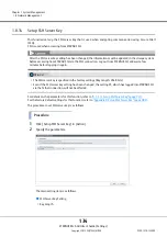
Page 134: ...x B Setup SSH Server Key page 982 The procedure to set SSH server key is as follows Procedure 1 Click Setup SSH Server Key in Action 2 Specify the parameters The main setting item is as follows SSH Server Key Setting Key Length After the SSH server key setting has been changed the information must be updated in the storage system before accessing from ETERNUS CLI via the SSH connection Log out fro...

Page 135: ... is created by using this function and the SSL server certificate is created by using the procedure in 1 8 16 Create Key CSR page 137 Register one of the certificates in the ETERNUS DX when using the HTTPS connection After the SSL server key and the self signed SSL certificate have been created the information must be updated in the storage system before accessing from ETERNUS Web GUI via the HTTP...

Page 136: ...icate in Action 2 Specify the parameters The main setting items are as follows Create Self signed SSL Certificate Setting Key Length Common Name Subject Alt Name 3 Click the Create button A confirmation screen appears 4 Click the OK button Creation of the self signed SSL certificate starts If an error screen appears under the following conditions check the parameter settings When items do not sati...

Page 137: ...er key or SSL server certificate the information must be updated in the ETERNUS DX before being accessed from ETERNUS Web GUI via the HTTPS connection Log out from ETERNUS Web GUI and wait a few minutes before logging in again Check the necessary items for authentication beforehand When using the key server for SED authentication key management a self signed SSL certificate or an SSL server certif...

Page 138: ...e Name Locality Name Organization Name Organization Unit Name Common Name Subject Alt Name 3 Click the Create button A confirmation screen appears 4 Click the OK button The creation of the CSR starts When the creation of the CSR is complete the screen for downloading the file is displayed If an error screen appears under the following conditions check the parameter settings When items do not satis...

Page 139: ...file appears 7 Save both the key file and the CSR file The default key file name is ServerKey_serial number for the ETERNUS DX_YYYY MM DD_hh mm ss txt The default CSR file name is ServerCsr_serial number for the ETERNUS DX_YYYY MM DD_hh mm ss txt YYYY MM DD_hh mm ss the date and time when the download screen Step 5 is displayed The files are saved 8 Click the Done button to return to the Network s...

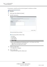
Page 140: ...egister one of the certificates in the ETERNUS DX when using the HTTPS connection To obtain the SSL server certificate the Certificate Signing Request CSR that is downloaded using the procedure in 1 8 16 Create Key CSR page 137 must be send to the certification authority Register the SSL server key and the SSL server certificate as a pair in the ETERNUS DX If the combination of the SSL server key ...

Page 141: ...Guide Settings Copyright 2015 FUJITSU LIMITED P2X0 1270 13ENZ0 141 2 Click the Browse button to specify the path to the SSL Server Key File The main setting item is as follows Register SSL Certificate Setting SSL Server Key File 3 Click the Import button Imported is displayed ...

Page 142: ...ttings Copyright 2015 FUJITSU LIMITED P2X0 1270 13ENZ0 142 4 Click the Browse button to specify the path to the SSL Server Certificate File The main setting item is as follows Register SSL Certificate Setting SSL Server Certificate File 5 Click the Import button Imported is displayed ...

Page 143: ... return to the Network screen End of procedure If an error screen appears under the following conditions check the parameter settings When the imported file was not the SSL server key file When the imported file was not the SSL server certificate file When the imported SSL server certificate file was not the certificate which corresponds to the SSL server key After registering the SSL server key o...

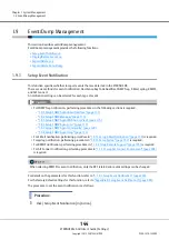
Page 144: ...function refer to Appendix B Setup Event Notification page 983 The procedure to set the event notification is as follows Procedure 1 Click Setup Event Notification in Action For SNMP Trap notification performing procedures in the following sections is required 1 8 3 Setup SNMP Agent Basic Interface page 111 1 8 4 Setup SNMP Manager page 113 1 8 5 Setup SNMP Agent MIB Access View page 115 1 8 6 Set...

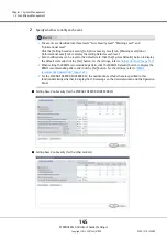
Page 145: ...evel tab or Informational Level tab to display the setting fields for each level Event notifications can be reset to the default state Click the System Defaults button to display the default state and click the Set button For the settings refer to Initial state list page 741 When setting the REMCS recommended pattern click the REMCS Defaults button to display the REMCS recommended pattern and clic...

Page 146: ...nt ETERNUS Web GUI User s Guide Settings Copyright 2015 FUJITSU LIMITED P2X0 1270 13ENZ0 146 The main setting items are as follows Setting based on Severity All Error Events All Warning Events All Informational Events Error Severity Level Warning Level ...

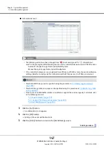
Page 147: ...utomatic Change Storage Cluster Active Standby State Manual Change Storage Cluster Active Standby State If the controller firmware version is updated from V10L2x to V10L30 or later the event notification settings whether to notify and the notification method that were set in V10L2x are retained Threshold of SDP usage can be specified using the procedure in 7 7 Modify Copy Parameters page 608 Thres...

Page 148: ...e related to configuration information changes such as module failures and volume creation Up to 1600 800 per CM event logs can be displayed Once the recorded event log is no longer required it can also be deleted Display event logs The procedure to display event logs is as follows Procedure 1 Click Display Delete Event Log in Action 2 Check the displayed event logs Even after deleting the event l...

Page 149: ... or degrade or when a temperature error is detected Messages that start with M are displayed when an event that requires maintenance occurs Messages that start with E are displayed when an error level event occurs Warning level Messages that start with J are displayed when components require maintenance or preven tive maintenance or unusual temperatures occur Messages that start with W are display...

Page 150: ... to suit the destination it is to be saved Exported Maintenance Information The storage system log includes internal log and configuration information Internal log Detected errors warnings and traces Configuration definition information Configuration information exported from the ETERNUS DX When an ETERNUS DX in a Unified Storage environment the storage system log and the NAS Engine log CM 0 CM 1 ...

Page 151: ...to export logs in the SAN environment is as follows Procedure 1 Click Export Delete Log in Action 2 Set the detailed information for exporting a log The main setting items are as follows Export Option Specify Time Range Start Time End Time Include I O Module log Log File Size Delete of Customer Information 3 Click the Export button A confirmation screen appears If an error screen appears under the...

Page 152: ...lg YYYY MM DD_hh mm ss the date and time when the download screen Step 5 is displayed When a log file is segmented the segmented log files are given the same name and num bered serially 01 If the log file is segmented download and save the next segment save all the segmented files When exporting the log is complete save the log file immediately If Non segmentation is selected in the Log File Size ...

Page 153: ...nified Storage environment is as follows Procedure 1 Click Export Delete Log in Action 2 Export the storage system log 2 1 Set the detailed information for exporting a log For setting items refer to Step 2 in For a SAN environment When exporting the log is complete make sure to export a panic dump In a Unified Storage environment when log files are exported while the ETERNUS DX is in a high load s...

Page 154: ... if a time period is specified for NAS Engine logs all of the NAS Engine logs in the ETERNUS DX are exported The customer information in the NAS Engine logs cannot be deleted If Yes is selected for this item the NAS Engine logs are not exported If an error screen appears under the following conditions check the parameter settings When the input date and or time are not valid For example February 3...

Page 155: ...en the same name and numbered serially 01 If the log file is segmented download and save the next segment save all the segmented files 3 Export the CM 0 NAS Engine log 3 1 Click the Export button A confirmation screen appears 3 2 Click the OK button Log export starts The progress screen is displayed After the log export is finished a screen to execute downloading the file is displayed When exporti...

Page 156: ... gz YYYY MM DD_hh mm ss the date and time when the download screen Step 3 3 is displayed x CM number When a log file is segmented the segmented log files are given the same name and numbered serially 01 If the log file is segmented download and save the next segment save all the segmented files When exporting the log is complete save the log file immediately When saving segmented log files make su...

Page 157: ... 1 Click the Export button A confirmation screen appears 4 2 Click the OK button Log export starts The progress screen is displayed After the log export is finished a screen to execute downloading the file is displayed 4 3 Click the Download button to save the exported log A dialog box to download the file appears When exporting the log is complete save the log file immediately ...

Page 158: ...saves the memory information of the Controller Module that is stored in the panic dump data in a segment size specified by the user An exported panic dump can be stored on a floppy disk or hard disk or sent by E mail Panic dump is used to analyze the cause of a firmware abnormality or hardware error For details on the parameters for this function refer to A 1 8 3 Export Delete Panic Dump page 750 ...

Page 159: ...elete Panic Dump in Action 2 Specify the panic dump to be exported and the segment file size The main setting items are as follows Panic Dumps Panic Dumps Option Dump File Segment Size 3 Click the Export button A confirmation screen appears 4 Click the OK button Exporting of the panic dump starts The progress screen is displayed After the panic dump export is finished a screen to execute downloadi...

Page 160: ...her models Panic_serial number for the ETERNUS DX_YYYY MM DD_hh mm ss_CMy_serial number for panic dump file zlg YYYY MM DD_hh mm ss the date and time when the panic has occurred y CM number in which the panic has occurred When a panic dump file is segmented the segmented panic dump files are given the same name and numbered serially 01 If the panic dump file is segmented download and save the next...

Page 161: ...t Dump Management ETERNUS Web GUI User s Guide Settings Copyright 2015 FUJITSU LIMITED P2X0 1270 13ENZ0 161 7 Click the Finish button A confirmation screen appears 8 Click the OK button to return to the Event Dump screen End of procedure ...

Page 162: ...s Enable the Audit Log setting and then specify the destination external server Refer to 1 10 3 Setup Audit Log page 164 for details Audit logs are sent after the external server is specified Note that the ETERNUS DX does not save the audit log The audit log is only sent to the specified external server The conditions for collecting audit logs are as follows The interface must be ETERNUS Web GUI E...

Page 163: ...Log This function disables the audit log function For the factory default settings for this function refer to Appendix B Audit Log page 983 The procedure to disable the audit log function is as follows Procedure 1 Click Disable Audit Log in Action A confirmation screen appears 2 Click the OK button Disabling of the audit log starts 3 Click the Done button to return to the Audit Log screen End of p...

Page 164: ...Syslog server is specified Confirm that the audit log has been successfully sent to the Syslog server by logging in and out from ETERNUS Web GUI or ETERNUS CLI and performing a transmission test to the Syslog server Even if a communication error occurs between the ETERNUS DX and the Syslog server the audit log is not sent again Changing the Syslog server setting is only available when the Audit Lo...

Page 165: ...nfirmation screen appears 4 Click the OK button Setting of the audit log starts 5 Click the Done button to return to the Audit Log screen End of procedure If an error screen appears under the following conditions check the parameter settings When the Audit Log setting is Disable When the specified IP address of the Syslog server conflicts with the internal IP address of the ETERNUS DX Up to two Sy...

Page 166: ...gement Machine Name This function specifies the name of the key management device Key Management Machine The key management device name is used for the device that is to be used to connect to the key server For details on the parameters for this function refer to A 1 10 1 Setup Key Management Machine Name page 751 The procedure to set the key management device name is as follows Procedure 1 Click ...

Page 167: ...een appears 4 Click the OK button Setting of the key management device name starts 5 Click the Done button to return to the Key Management screen End of procedure Do not change the key management device name after the key status changes to Normal The key status can be checked on the Key Group screen Refer to Key Group in ETERNUS Web GUI User s Guide Operation for details If the entered Key Managem...

Page 168: ...er page 752 For the factory default settings for this function refer to Appendix B Add Key Server page 983 The procedure to add a key server is as follows Procedure 1 Click Add Key Server in Action 2 Specify the parameters The key server cannot be added when the common key 1 is not registered Refer to 1 4 7 Register SED Authentication Key page 47 for details 1 The common key for SEDs that are mana...

Page 169: ...lections can be made and click Delete Key Server in Action A confirmation screen appears If an error screen appears under the following conditions check the parameter settings When each parameter fails to satisfy the input conditions When inputting a domain name or an IP address that is already used for another key server When the IP address that was input and the IP address of the LAN port MNT or...

Page 170: ...ettings For details on the parameters for this function refer to A 1 10 3 Modify Key Server page 753 The procedure to change the key server settings is as follows Procedure 1 Select the key server that is to be changed and click Modify Key Server in Action Key server settings that are allocated to a key group can be changed This function can be used to change Domain Name IP Address Port No and LAN...

Page 171: ...ng of the key server settings starts 5 Click the Done button to return to the Key Management screen End of procedure If an error screen appears under the following conditions check the parameter settings When each parameter fails to satisfy the input conditions When inputting a domain name or an IP address that is already used for another key server When the IP address that was input and the IP ad...

Page 172: ...d Refer to 1 4 7 Register SED Authentication Key page 47 for details 1 The common key for SEDs that are managed in the ETERNUS DX S3 series The key group can be created even when the key server is not registered The key group can be created even when communication with the key server is not available Register RAID groups that use the same key in the key group Refer to 5 8 Set Key Group RAID Group ...

Page 173: ... Mode Key Server 3 Click the Create button A confirmation screen appears 4 Click the OK button Key group creation starts 5 Click the Done button to return to the Key Group screen End of procedure If an error screen appears under the following conditions check the parameter settings The Name is not entered The Storage System Group Name is not entered Each parameter fails to satisfy the input condit...

Page 174: ...rn to the Key Group screen End of procedure 1 11 7 Modify Key Group This function changes the key group settings The key group combines all of the RAID groups that use the same key For details on the parameters for this function refer to A 1 10 5 Modify Key Group page 757 The procedure to change the key group settings is as follows Procedure 1 Click Modify Key Group in Action A key group in which ...

Page 175: ...ppears 4 Click the OK button Changing of the key group settings starts 5 Click the Done button to return to the Key Group screen End of procedure If an error screen appears under the following conditions check the parameter settings When the Name is not entered When the Storage System Group Name is not entered When each parameter fails to satisfy the input conditions When the same server ID is spe...

Page 176: ...rformed In this case register the SSL certificate of the ETERNUS DX S3 series in the key server accept access from the ETERNUS DX S3 series and then update the key again The key status changes to Normal An SSL certifi cate of the ETERNUS DX S3 series indicates a self signed SSL certificate or an SSL server certificate The key can only be updated when the SEDs that configure the RAID groups in the ...

Page 177: ...n Key Setting Current Key 3 Click the Update button A confirmation screen appears 4 Click the OK button Updating of the SED Authentication Key starts 5 Click the Done button to return to the Key Group screen End of procedure If an error screen appears under the following conditions check the parameter settings When the master server for the key group is not registered When one of the following sta...

Page 178: ...A 1 10 7 Import SSL KMIP Certificate page 760 The procedure to register the SSL KMIP certificate is as follows Procedure 1 Click Import SSL KMIP Certificate in Action The SSL KMIP certificate cannot be registered when a common key 1 is not specified Refer to 1 4 7 Register SED Authentication Key page 47 for details 1 The common key for SEDs that are managed in the ETERNUS DX S3 series Export the S...

Page 179: ...k the Import button A confirmation screen appears 4 Click the OK button Importing of the SSL KMIP certificate starts 5 Click the Done button to return to the Key Group screen End of procedure If an error screen appears under the following conditions check the parameter settings When reading of the SSL KMIP Certificate failed When the SSL KMIP Certificate file is larger than 4096 bytes When the imp...

Page 180: ...to 16 storage systems can be specified as migration source storage systems Up to 8 migration paths can be specified per migration source storage system Up to 512 data migration LUNs can be specified per migration path To perform Storage Migration the destination storage systems the source storage systems and the destination volumes must satisfy the conditions below Requirements for a source storag...

Page 181: ...is attribute Volumes that have the mirroring reservation attribute can be checked in the Forbid Advanced Copy field on the Volume screen Refer to Volume Basic Information in ETERNUS Web GUI User s Guide Operation for details Stop access from the host to both the source LUN and destination volume When Migration Full Compare or Full Compare is specified for the operation mode stop the host access to...

Page 182: ...tting Files page 1074 for details 4 Stop access from the host to the source volume 5 Change the mode of the FC port used for migration in the destination storage system to Initiator 4 3 11 Modify Port Mode page 459 6 Set port parameters to the FC Initiator port 4 3 7 Modify FC Port Parameters page 441 7 Connect the source and destination storage systems using an FC cable or use a switch to connect...

Page 183: ...n is displayed when the Storage Migration setting file is in the following conditions The Storage Migration setting file is not specified A character code other than the space or tab is placed before the keyword on the left of The number of the parameters on the right of does not coincided with the specified number of parameters of the keyword The identification code is invalid Type is not Open Th...

Page 184: ... is not a decimal or 4 digit hexadecimal number The volume number is out of range Not specified The status is abnormal The volume type is not Standard WSV TPV or FTV The destination volume is used redundantly in the Storage Migration setting file The destination volume is already used in a Storage Migration in execution The source World Wide Name WWN being set for PATH is in the following conditio...

Page 185: ...Path Group Detail Information screen Refer to Path Group Detail Information in ETERNUS Web GUI User s Guide Operation for display items If a CE number is not specified for the migration path in the ETERNUS DX8700 S3 DX8900 S3 CE 0 is assumed as specified To change the CE number cancel the process edit the Storage Migration setting file and then restart this function Refer to the Storage Migration ...

Page 186: ...e WWN source LUN and destination volumes The procedure to download the template is as follows Procedure 1 Click Download Template in Action 2 Click the Download button A confirmation screen appears 3 Click the OK button A dialog box to download file appears 4 Save the template file The default file name is StMigTemplate txt Downloading of the template file starts 5 Click the Close button to return...

Page 187: ...are deleted Hot controller firmware upgrade is being performed in the destination storage system Eco mode schedule setting of the RAID group to which the destination volume belongs Eco mode schedule setting of the Thin Provisioning Pool TPP to which the destination volume belongs Capacity expansion of the RAID group to which the destination volume belongs RAID migration of the destination volume E...

Page 188: ...lt file The default file name is StMigResult_serial number for the ETERNUS DX_YYYY MM DD_hh mm ss txt YYYY MM DD_hh mm ss the date and time when the download screen Step 2 is displayed Downloading of the Storage Migration result file starts 5 Click the Close button to return to the Path Group Detail Information screen End of procedure Download of Storage Migration results is made in path group uni...

Page 189: ...Storage Migration is restarted in volume units Storage Migration can be restarted when its Migration Status is Suspend Stop or Error If Storage Migration is restarted when its Migration Status is Suspend or Error data migration is started from the point of LUN suspension If Storage Migration is restarted when its Migration Status is Stop data migration of the LUN is started over from scratch Resta...

Page 190: ...n to return to the Path Group Detail Information screen End of procedure Storage Migration is suspended in volume units Storage Migration can be suspended when its Migration Status is Waiting or Running A suspended Storage Migration can be restarted Refer to 1 12 5 Restart Storage Migration page 189 for details Suspend cannot be clicked if one or more source LUNs are selected for which the migrati...

Page 191: ...utton to return to the Path Group Detail Information screen End of procedure Storage Migration is stopped in volume units Storage Migration can be stopped when its Migration Status is Waiting Running Suspend or Error A stopped Storage Migration can be restarted Refer to 1 12 5 Restart Storage Migration page 189 for details Stop cannot be clicked if one or more source LUNs are selected for which th...

Page 192: ...munication Log This function displays the communication log between the ETERNUS DX and REMCS center using the Remote Support function When the Remote Support function cannot be operated properly for example cannot be connected to the REMCS center use this log to identify the cause of the problem The communication log includes requests from the ETERNUS DX to the server and responses from the server...

Page 193: ...ed by Fujitsu REMCS provides maintenance functions as follows Failure Notice This function reports various failures that occur in the ETERNUS DX to the REMCS center The maintenance engineer is notified of a failure immediately Information Transfer This function sends information such as logs and configuration information to be used when checking a failure It reduces the time required to collect in...

Page 194: ...addresses for the IP addresses of the proxy server the SMTP server the POP server and the HTTP server IPv6 addresses cannot be used When changing the registered information use the procedure in 1 13 3 Update Customer Information page 196 and the 1 13 4 Update Communication Environment Information page 198 The information files customer information file and communication environment information fil...

Page 195: ... Setting of the remote support starts Refer to Step 2 in the 1 13 3 Update Customer Information page 196 for setting items Refer to Step 2 in the 1 13 4 Update Communication Environment Information page 198 for setting items If an error screen appears under the following conditions check the parameter settings The required items are not specified Wrong values are entered When MNT is specified for ...

Page 196: ...setting results If the settings in 1 13 2 Setup Remote Support page 193 has not been completed in advance this function cannot be used When Remote Support is Stopped customer information cannot be updated Customer information saved in the ETERNUS DX 1 can be deleted after transmitting the information to the REMCS center Select the Delete any Customer Identity information from the storage system af...

Page 197: ...mation File Customer Information Detailed Settings Checkbox Company Name Department Division Address Building Name Administrator Name Administrator E Mail Address Postal Code Zip Code Phone Number FAX Number Storage System Unique Name Country of Installation ISO3166 A2 Example JP US DE etc Installation Location Address Building Name If the wrong information file is selected and the Import button i...

Page 198: ...ter For details on the parameters for this function refer to A 1 12 3 Update Communication Environment Information page 768 If the Set button is clicked under the following conditions an error screen appears Check the parameter settings The required items are not specified Wrong values are entered If the settings in 1 13 2 Setup Remote Support page 193 has not been completed in advance this functi...

Page 199: ... Specify the parameters The main setting items are as follows Information File Communication Environment Information File Communication Environment Information Connection Service Proxy Server SMTP Server SMTP Authentication Information REMCS Center Detailed Configuration Information If the wrong information file is selected and the Import button is clicked an error screen appears Check the paramet...

Page 200: ... screen appears under the following conditions check the parameter settings The required items are not specified Wrong values are entered When MNT is specified for the LAN Port used for Remote Support and when the IP Address of the Proxy server SMTP server POP server is the same as the broadcast address of the MNT port When RMT is specified for the LAN Port used for Remote Support and the IP Addre...

Page 201: ...or this function refer to A 1 12 4 Setup Log Sending Parameters page 773 For the factory default settings for this function refer to Appendix B Setup Log Sending Parameters page 986 The procedure to send log is as follows Configure Automatic Log Transmission The ETERNUS DX sends log periodically or when an event occurs Procedure 1 Click Setup Log Sending Parameters in Action 2 Specify the paramete...

Page 202: ...eriod Day of the Week 3 Click the Set button A confirmation screen appears 4 Click the OK button The parameter settings of log transmission Automatic Log Transmission are updated in the storage system 5 Click the Done button to return to the screen when starting this function in Step 1 End of procedure Immediately Send Log Manually In this screen send log manually and immediately Procedure 1 Click...

Page 203: ...5 Click the OK button Log transmission Immediately Send Log Manually is executed 6 Click the Done button to return to the screen when starting this function in Step 1 End of procedure If an error screen appears under the following conditions check the parameter settings The incident number has not been entered or is incorrect When Specify has been selected for Time Range Specified but the start ti...

Page 204: ...ort can be stopped only when it is Operating The procedure to stop Remote Support is as follows Procedure 1 Click Stop Restart Remote Support in Action The current Remote Support status is displayed 2 Click the Stop button A confirmation screen appears REMCS cannot be used when the AIS Connect function is being used Disable the AIS Connect function and then restart the remote support REMCS Refer t...

Page 205: ...cedure Restarting Remote Support This function restarts the Remote Support The Remote Support can be restarted only when it is Stopped The procedure to restart Remote Support is as follows Procedure 1 Click Stop Restart Remote Support in Action The current Remote Support status is displayed 2 Click the Restart button A confirmation screen appears 3 Click the OK button The Remote Support is restart...

Page 206: ...lt settings for this function refer to Appendix B Setup AIS Connect Environment page 986 The procedure to set the AIS Connect information is as follows Procedure 1 Click Setup AIS Connect Environment in Action AIS Connect is not available when REMCS is being used Suspend REMCS and then enable AIS Connect Refer to 1 13 6 Stop Restart Remote Support page 204 for details for regions other than EMEA B...

Page 207: ...is clicked The Setup AIS Connect Environment screen appears Proceed to Step 3 When the I decline button is clicked Returns to the screen when starting this function in Step 1 3 Specify the parameters The terms and conditions regarding the handling of personal information are displayed only when Country of Installation Country Code Country Name is not specified To print the terms and conditions reg...

Page 208: ...The IP address for Proxy Server and the network address for the MNT port or the RMT port are the same The IP address for Proxy Server and the broadcast address for the MNT port or the RMT port are the same The same IP address is specified for Proxy Server and AIS Connect Server Either of the Proxy Server or the Port No has been specified Port No does not satisfy the input conditions User Name is n...

Page 209: ...mote Session Permission in Action Settings can be changed when AIS Connect is enabled Refer to 1 14 1 Setup AIS Connect Environment page 206 for details The permission setting of a remote session is released if one of the following conditions applies When a remote session is not detected before the timeout period that is specified for the timeout setting When this function forbids remote sessions ...

Page 210: ...tion in Step 1 End of procedure 1 14 3 Send Log This function manually sends a storage system log to the remote server AIS Connect server when the AIS Connect function is in operation Sending logs is only available when AIS Connect is enabled Refer to 1 14 1 Setup AIS Connect Environment page 206 for details Check the connection to the AIS Connect server in advance Refer to 1 14 4 Test Server Conn...

Page 211: ...tion status between the ETERNUS DX and a remote server AIS Connect server This function collects logs including I O Module logs at the time when performing the Send Log function Log files are divided into 640MB increments and sent to the AIS Connect server Checking the connection status is only available when AIS Connect is enabled Refer to 1 14 1 Setup AIS Connect Environment page 206 for details...

Page 212: ... the AIS Connect server is as follows Procedure 1 Click Send AIS Connect Test Event in Action A confirmation screen appears The check result of the server connection status is displayed in the Test Server Connectivity Result screen If server connection fails the cause of the error is displayed Sending a test event is only available when AIS Connect is enabled Refer to 1 14 1 Setup AIS Connect Envi...

Page 213: ...y registered in the ETERNUS DX Check the expiration date of the default root certificate from the Root Certificate screen The root certificate must be updated before the expiration date This function overwrites the root certificate Only the latest root certificate is saved in the ETERNUS DX The root certificate cannot be updated when both the AIS Connect setting and the SSL Server Certification se...

Page 214: ... File 3 Click the Import button A confirmation screen appears 4 Click the OK button Updating of the root certificate starts 5 Click the Done button to return to the Root Certificate screen End of procedure If an error screen appears under the following conditions check the parameter settings When the imported file is not root certificate file When the imported file size exceeds 12288 bytes When bo...

Page 215: ... the online mode may not be possible if the storage system status does not allow the firmware to be applied Check the storage system status or contact a maintenance engineer The ETERNUS DX may be rebooted after the controller firmware is applied Access from hosts is not possible while rebooting is in progress Make sure to stop any access from hosts before applying controller firmware This function...

Page 216: ...Suspend or Error Suspend The mirror status of the REC buffer that is being used is Recovering and the session status is not Suspend or Error Suspend REC sessions in which status is not Suspend or Error Suspend exist offline update is not available The following conditions must be satisfied when applying a controller firmware that is older than the current one To apply the older controller firmware...

Page 217: ...troller Firmware Archive Settings Controller Firmware Archive Schedule Settings Apply Date 3 Click the Next button A confirmation screen appears If an error screen appears under the following conditions check the parameter settings Controller Firmware Archive is not specified when Set File is selected Apply Date does not satisfy the input conditions when Set Date is selected A date that is earlier...

Page 218: ...pending on the selected apply date When Apply Now is selected The Apply Immediate Apply screen appears Proceed to Step 6 When Set Date is selected The Apply Specific Date screen appears Proceed to Step 9 When applying a controller firmware that is older than the current controller firmware A confirmation screen to apply the older controller firmware appears 5 Click the OK button The screen that is...

Page 219: ... User s Guide Settings Copyright 2015 FUJITSU LIMITED P2X0 1270 13ENZ0 219 6 Check the controller firmware application information and the application mode When the application mode is Update When the application mode is Update for applying the older controller firmware ...

Page 220: ... User s Guide Settings Copyright 2015 FUJITSU LIMITED P2X0 1270 13ENZ0 220 When the application mode is Update Reboot When the application mode is Update Reboot for applying the older controller firmware The main setting items are as follows Apply Mode Check Apply Mode ...

Page 221: ...r firmware starts Update or Update Reboot is displayed as the application mode Which one is displayed depends on the storage system status If Update Reboot is displayed and the Apply button is clicked the ETERNUS DX automatically reboots after the controller firmware is applied Click the Rediscovery button to display the latest information the application mode and the status check result Never tur...

Page 222: ...s Copyright 2015 FUJITSU LIMITED P2X0 1270 13ENZ0 222 9 Click the Done button to return to the Firmware Maintenance screen When Apply Now is selected When the application mode is Update When the application mode is Update Reboot When Set Date is selected When the application mode is Update ...

Page 223: ...ettings Copyright 2015 FUJITSU LIMITED P2X0 1270 13ENZ0 223 When the application mode is Update for applying the older controller firmware When the application mode is Update Reboot When the application mode is Update Reboot for applying the older controller firmware End of procedure ...

Page 224: ... data exists in the ETERNUS DX The start time to apply controller firmware when the application mode is Update The storage system is not in normal status The battery status is not Full Charge REC sessions with the following conditions appear A blocked copy path is being used and the session status is not Suspend or Error Suspend The mirror status of the REC buffer that is being used is Recovering ...

Page 225: ...e procedure to delete the application schedule for controller firmware is as follows Procedure 1 Click Delete Firmware Schedule in Action A confirmation screen appears 2 Click the OK button Deletion of the application schedule for the controller firmware starts 3 Click the Done button to return to the Firmware Maintenance screen End of procedure ...

Page 226: ...ion area for Component Display function Assign Global Hot Spare Drives Release Global Hot Spare Assign Dedicated Hot Spare Release Dedicated Hot Spare Turn on Locator Beacon Turn off Locator Beacon Controller Enclosure Add Drive Enclosure Drive Enclosure Add Channel Adapter Port Channel Adapter NAS Recovery Management Force Enable Module Controller Module Recover NAS Engine Recover NAS System Volu...

Page 227: ...pares Make sure to register a Global Hot Spare with the same or a larger capacity than the data drives If the Global Hot Spare capacity is smaller than the data drive the drive does not work as the hot spare When a mix of Online disks Nearline disks SSDs Online SEDs Nearline SEDs and SSD SEDs is installed together in the ETERNUS DX Global Hot Spare of each type is required Register the Global Hot ...

Page 228: ...ocedure to register a Global Hot Spare is as follows Procedure 1 Select a drive that is to be used as a Global Hot Spare multiple selections can be made and click Assign Global HS in Action A confirmation screen appears 2 Click the OK button Registration of the Global Hot Spare starts 3 Click the Done button to return to the Drives screen End of procedure ...

Page 229: ... a data drive or Dedicated Hot Spare for a different RAID group The procedure to release a Global Hot Spare is as follows Procedure 1 Select a drive multiple selections can be made that is to be released from being a Global Hot Spare and click Release Global HS in Action A confirmation screen appears 2 Click the OK button Releasing of the Global Hot Spare starts 3 Click the Done button to return t...

Page 230: ...Spare 1 Copybackless is a function that mounts a hot spare in the RAID group instead of the failed drive The replaced drive is then used as a hot spare This function makes Copyback unnecessary Drives that are currently used cannot be registered as Dedicated Hot Spares Make sure to register a Dedicated Hot Spare with the same or a larger capacity than the data drives If the Dedicated Hot Spare capa...

Page 231: ... the Dedicated Hot Spare is registered for a RAID group to which a failed drive belongs the Dedicated Hot Spare is used before the Global Hot Spare If there is no unused Dedicated Hot Spare and the drive fails the Global Hot Spare is used Hot Spares can be registered in any slots of the CEs only for the ETERNUS DX60 S3 DX100 S3 DX200 S3 and the ETERNUS DX200F and the DEs To use the Copybackless fu...

Page 232: ...he Assign RAID Group field the drive type registered in the RAID group is displayed If multiple drive types are used in the ETERNUS DX the drive type is displayed as described below If only Online type drives are used or if both Online and Nearline type drives are used Online is displayed If only Online SED type drives are used or if both Online SED and Nearline SED type drives are used Online SED...

Page 233: ...rive Global Hot Spare or Dedicated Hot Spare for a different RAID group The procedure to release a Dedicated Hot Spare is as follows Procedure 1 Select a drive multiple selections can be made that is to be released from being a Dedicated Hot Spare and click Release Dedicated HS in Action A confirmation screen appears 2 Click the OK button Releasing of the Dedicated Hot Spare starts 3 Click the Don...

Page 234: ...linked turned off Note that the option to turn on off the LEDs for a specific component is not available Instructing the CE LEDs to turn on off is performed by using the Controller Enclosure screen Refer to Controller Enclosure in ETERNUS Web GUI User s Guide Opera tion for details When the LEDs in the DE are instructed to turn on off the LEDs on the front cover of the DE the IOM LEDs on the rear ...

Page 235: ...n A confirmation screen appears 2 Click the OK button The locator beacon is turned on 3 Click the Done button to return to the screen when starting this function in Step 1 End of procedure Turning off the LED The procedure to turn off an LED is as follows Procedure 1 Click Turn off locator beacon in Action A confirmation screen appears If the LED is already turned on Turn on locator beacon cannot ...

Page 236: ...ff Locator Beacon ETERNUS Web GUI User s Guide Settings Copyright 2015 FUJITSU LIMITED P2X0 1270 13ENZ0 236 2 Click the OK button The locator beacon is turned off 3 Click the Done button to return to the screen when starting this function in Step 1 End of procedure ...

Page 237: ...o use this function with the ETERNUS DX500 S3 DX600 S3 and the ETERNUS DX8700 S3 DX8900 S3 a user account with the Maintainer default role or Maintenance Operation policy is required When DE hot expansion is performed multiple DEs can be added with a single operation 2 5 DEs 3 5 DEs and 3 5 high density DEs can be installed in the same ETERNUS DX S3 series except the ETERNUS DX60 S3 For the ETERNU...

Page 238: ... 2015 FUJITSU LIMITED P2X0 1270 13ENZ0 238 2 Specify the parameters The main setting item is as follows Target Drive Enclosure Type 3 Click the Next button The Place DE on the rack screen appears 4 Add the DE according to the installation procedure and click the Next button The Enable DE screen appears ...

Page 239: ...User s Guide Settings Copyright 2015 FUJITSU LIMITED P2X0 1270 13ENZ0 239 5 After the DEs are activated isolate IOM 1 The Disable IOM 1 screen appears 6 Check the status of the target components and then click the Next button The Check Disable IOM 1 Progress screen appears ...

Page 240: ...ide Settings Copyright 2015 FUJITSU LIMITED P2X0 1270 13ENZ0 240 7 After IOM 1 is isolated disconnect the SAS cables The Detach Cable screen appears 8 Disconnect the SAS cables by following the disconnection procedure and then click the Next button The Connect Cable screen appears ...

Page 241: ...0 13ENZ0 241 9 Connect the SAS cables by following the connection procedure and then click the Next button The Enable IOM 1 screen appears 10 Activate the IOM 1 according to the installation procedure and click the Next button The Finish screen appears 11 Click the Done button to return to the Drive Enclosure screen End of procedure ...

Page 242: ...installed in the ETERNUS DX100 S3 1 CAs with the minimum number of ports that can be installed in the ETERNUS DX60 S3 DX100 S3 1 port types and 2 port types are available This function is available only when the ETERNUS DX60 S3 DX100 S3 has a minimum port type CA Input the license key for each host interface with the minimum port type and then add the port The following examples explain how the mi...

Page 243: ...n The displayed screen may vary depending on whether the installation of license key is required or not When the license key is not registered The Register license of additional Channel Adapter Port screen appears Proceed to Step 3 When the license key is already registered The Define additional Channel Adapter port screen appears Proceed to Step 5 3 Input the license key ...

Page 244: ...ton The operations and displayed screen vary depending on the host interface type that is used For FC FCoE 10G iSCSI or 10G NAS host interface The installation of SFP starts and the Check SFP Installation screen appears After the installation of the SFP is complete when the CA includes an SFP the installation of the CA port starts and the Status Check screen appears After the installation of the C...

Page 245: ...be enabled without replacing it called force enable hereinafter The procedure to perform force enable is as follows Procedure 1 Select the component to perform the force enable on and click Force Enable in Action A confirmation screen appears 2 Click the OK button The force enable starts The ETERNUS DX60 S3 the ETERNUS DX8700 S3 DX8900 S3 and the ETERNUS DX200F do not support the NAS recovery mana...

Page 246: ...manage the file system If a malfunction occurs in the NAS Engine due to an inconsistency between the management data and the RootFS use this function to recover the file system management area This function is displayed in a Unified Storage environment The procedure to recover the file system management area in the NAS system volume is as follows Procedure 1 Select the NAS Engine that is to be rec...

Page 247: ... both RootFSs use this function to recover the RootFS and forcibly enable the NAS Engine again This function is displayed in a Unified Storage environment The procedure to recover the NAS system volume is as follows Procedure 1 Select the NAS Engine that is to be recovered and click Recover NAS System Volume in Action A confirmation screen appears 2 Click the OK button Recovery of the NAS system v...

Page 248: ...13ENZ0 248 2 9 Export Performance Information This function exports the following performance information in a single operation and saves it as a text file Performance Host I O Performance Advanced Copy Performance CA Performance CM Performance Drive Performance PCIe Flash Module Refer to 3 16 Export Performance Information page 321 for details ...

Page 249: ...e drives The procedure to delete error information from all the drives is as follows Procedure 1 Click Clear All Error in Action A confirmation screen appears 2 Click the OK button Deletion of the error information from all the drives starts 3 Click the Done button to return to the Drive Error Statistics screen End of procedure This function can be performed without selecting the drive to delete e...

Page 250: ...rive The procedure to delete error information from the selected drive is as follows Procedure 1 Select the drive to delete error information from multiple selections can be made and click Clear Error in Action A confirmation screen appears 2 Click the OK button Deletion of the error information from the selected drive starts 3 Click the Done button to return to the Drive Error Statistics screen E...

Page 251: ...Management Expand Thin Provisioning Volume Volume Basic Information Modify Thin Provisioning Volume Threshold Optimize TPV FTV Capacity Cancel Optimizing TPV FTV Capacity Start Balancing Thin Provisioning Volume Balancing Thin Provisioning Volume Stop Balancing Thin Provisioning Volume Reconfigure NAS Volume Volume Basic Information Set Allocation SDV SDPV Management Delete Snap Data Pool Volume V...

Page 252: ...b GUI User s Guide Settings Copyright 2015 FUJITSU LIMITED P2X0 1270 13ENZ0 252 Snapshot Management for NAS Volumes Set Snapshot Snapshot Delete Snapshot Start Snapshot Stop Snapshot Functions in the Action area for Volume Display function ...

Page 253: ... in RAID groups Snap Data Pool Volume SDPV Volumes used as expansion areas for SDV that are created in RAID groups NAS Volume Volumes used for NAS system operation hereinafter referred to as NAS user volume in the Unified Storage environment that are created in TPPs The NAS function cannot be used for the ETERNUS DX60 S3 the ETERNUS DX8700 S3 DX8900 S3 and the ETERNUS DX200F The encryption functio...

Page 254: ... to be created one at a time Multiple volumes cannot be created when specifying the volume number for a new volume 1 Volumes can be created manually for WSV type volumes or when drives are selected manually to create Standard TPV SDV or SDPV type volumes Refer to Manually selecting destinations to create volumes page 263 for details When Automatic is selected to create a volume or when Manual is s...

Page 255: ...ual The conditions for RAID groups to configure WSVs are as follows The RAID level RAID1 0 RAID5 RAID6 RAID5 0 RAID1 RAID0 must be the same The number of member drives in the RAID group must be the same The Stripe Depth value must be the same The drive type Online Nearline SSD Online SED Nearline SED SSD SED must be the same Since the access performance of WSVs is reduced selecting the same drive ...

Page 256: ...the maximum pool capacity specified in 6 1 Set Thin Provisioning page 557 1 300GB of the created volume is used as the system area The capacity that can be used is specified capacity 300GB 2 The maximum number of NAS user volumes after the existing controller firmware is updated to V10L33 or later 3 The maximum number of NAS user volumes when the ETERNUS DX is shipped from the factory or the maxim...

Page 257: ...olume creation is not completed successfully When the NAS volume creation is not completed successfully perform the following actions 1 Confirm that the general status detail of the ETERNUS DX and the status of the NAS Engine are both Normal If the status is not Normal the ETERNUS DX requires maintenance The ETERNUS DX general status detail can be checked in the Storage screen Refer to Storage Bas...

Page 258: ...ied for TPV 2 1 fixed for NAS Setting items Standard TPV NAS SDV SDPV Remarks New Volume Name Capacity Type Capacity of source volume only SDV Allocation NAS FS Block Size 1 RAID Group TPP Selection Automatic Data Integrity Automatic Setting Drive Type RAID Level Key Group This item is available if the drive type is Online SED Nearline SED or SSD SED Number of Volumes 2 Encryption by CM Off fixed ...

Page 259: ...g Select RAID Group Information field 2 The NAS FS block size cannot be specified for TPV 3 The number of volumes cannot be specified for NAS Setting items Standard TPV NAS SDV SDPV WSV 1 Remarks New Volume Name Capacity Type Capacity of source volume only SDV Allocation NAS FS Block Size 2 RAID Group TPP Selection Manual Data Integrity Manual Setting or Manual Setting Volume Information Use all L...

Page 260: ...e NAS FS block size cannot be specified for TPV 3 The number of volumes cannot be specified for NAS Setting items Standard TPV NAS SDV SDPV WSV 1 Remarks New Volume Name Capacity Type Capacity of source volume only SDV Allocation NAS FS Block Size 2 RAID Group TPP Selection Manual Data Integrity Manual Setting or Manual Setting Volume Information Use all Largest Free Space Volume No Encryption by ...

Page 261: ...e Information field Stripe Depth under the Manual Setting Select RAID Group Information field Setting items Standard SDPV WSV 1 Remarks New Volume Name Capacity Type Capacity of source volume only SDV Allocation RAID Group TPP Selection Manual Data Integrity Manual Setting or Manual Setting Volume Information Use all Largest Free Space Volume No Encryption by CM Off fixed when the encryption mode ...

Page 262: ...The procedure to create volumes by selecting destinations automatically is as follows Procedure 1 Click Create in Action 2 Select Automatic for RAID Group TPP Selection 3 Specify the volume detailed information The main setting items are as follows New Volume Name Capacity Type Capacity of source volume only SDV Allocation not displayed for the ETERNUS DX60 S3 NAS FS Block Size Data Integrity not ...

Page 263: ...ing RAID group Creating TPVs or NAS volumes in an existing TPP Creating WSVs in an existing RAID group If an error screen appears under the following conditions check the parameter settings The Name is not entered The Name does not satisfy the input conditions The Capacity is not entered The Capacity does not satisfy the input conditions The SDPV capacity that is specified for Capacity is not a mu...

Page 264: ...es page 254 The procedure to create Standard SDV or SDPV type volume in the existing RAID group is as follows Procedure 1 Click Create in Action 2 Select Manual for RAID Group TPP Selection 3 Specify the detailed information of new volumes and select the RAID group in which the volumes are to be created The main setting items are as follows New Volume Name Capacity Type Capacity of source volume o...

Page 265: ...SED type drives are used Online SED is displayed If a single SSD type SSD M SSD is used or if multiple SSD types SSD M SSD are used SSD is displayed If an error screen appears under the following conditions check the parameter settings The Name is not entered The Name does not satisfy the input conditions The SDPV capacity that is specified for Capacity is not a multiple of the SDPE capacity 1GB 2...

Page 266: ...V type volumes page 255 The procedure to create TPV type volume in the existing TPP is as follows Procedure 1 Click Create in Action 2 Select Manual for RAID Group TPP Selection 3 Specify the detailed information of new volumes and select the TPP in which the volumes are to be created The main setting items are as follows New Volume Name Capacity Type Allocation not displayed for the ETERNUS DX60 ...

Page 267: ...Nearline SED type drives are used Online SED is displayed If a single SSD type SSD M SSD is used or if multiple SSD types SSD M SSD are used SSD is displayed When creating a TPV the Encryption by CM setting cannot be changed If an error screen appears under the following conditions check the parameter settings The Name is not entered The Name does not satisfy the input conditions The Capacity does...

Page 268: ...e concatenated For detailed information about creating WSV type volumes refer to Creating WSV type volumes page 255 The procedure to create WSV type volume in the existing RAID group is as follows Procedure 1 Click Create in Action 2 Enter details of the volumes to be created and the selection information for the RAID group where the volumes are created The main setting items are as follows New Vo...

Page 269: ...elections can be made The main setting item is as follows Select RAID Groups Checkbox to select RAID groups When specifying the volume number select the Set Value checkbox and input the volume number When using the maximum free space in the selected RAID group to create WSVs without specifying the capacity select the Enable checkbox for Use all Largest Free Space and then input the number of WSVs ...

Page 270: ...or less The Enable checkbox for Use all Largest Free Space is selected and the capacity of the created WSV is larger than the maximum capacity The Set Value checkbox is selected and Volume No is not entered The input value of Volume No exceeds the settable range The Volume No is specified and Number of Volumes is not 1 The Number of Concatenation RAID Groups field is left blank 1 is specified or a...

Page 271: ...nt 3 1 Create Volume ETERNUS Web GUI User s Guide Settings Copyright 2015 FUJITSU LIMITED P2X0 1270 13ENZ0 271 7 Click the OK button Volume creation starts 8 Click the Done button to return to the Volume screen End of procedure ...

Page 272: ...uster function By repeating creation and deletion of volumes free space may be dispersed in the RAID group Up to 128 volumes can be deleted at once When deleting SDPVs refer to 3 8 1 Delete Snap Data Pool Volume page 298 or 3 8 2 Force Delete Snap Data Pool Volume page 299 This function can be used to delete an ODX Buffer volume The NAS system volumes can be deleted by ETERNUS CLI Note that the Ma...

Page 273: ...ort w or CM y CA z Port w is displayed in the LUN Group field in Step 1 or Step 3 the volume is mapped with applications other than ETERNUS Web GUI Use the relevant application to delete the volume from the port mapping information 6 Confirm that LUN Group Count is 0 in the LUN Group field under the Volume navigation 7 Use this function to delete volumes It is not necessary to delete a host affini...

Page 274: ... as follows Procedure 1 Select the volume to be renamed multiple selections can be made and click Rename in Action 2 Input the new volume Name and the Start of Suffix only when multiple volumes are selected The main setting items are as follows Rename Setting Name Start of Suffix For the ETERNUS DX8700 S3 DX8900 S3 up to 1024 volumes can be renamed at a time Note that this limita tion does not app...

Page 275: ... to return to the Volume screen End of procedure If an error screen appears under the following conditions check the parameter settings When the volume name is not input When the Name does not satisfy the input conditions When the Name overlaps with an existing volume name when selecting a single volume When the Start of Suffix is not input when selecting multiple volumes When the Start of Suffix ...

Page 276: ...nosis is being performed in the ETERNUS DX When pinned data exists in the ETERNUS DX The following volumes cannot be formatted Volumes for which Status is Broken Data Lost or Not Ready Volumes undergoing RAID migration A copy source volume or a copy destination volume of an Advanced Copy local remote that is being performed Volumes registered in a RAID group undergoing Logical Device Expansion LDE...

Page 277: ... Click the Done button to return to the Volume screen End of procedure The Format button cannot be clicked under the following conditions Volumes that are used for the Virtual Volume function is selected FTV type volumes where the usage is System is selected For the ETERNUS DX8700 S3 DX8900 S3 more than 1024 volumes are selected If the format target TPV fulfills all of the following conditions an ...

Page 278: ...r larger When the concatenation source volume is a concatenated volume the volume must satisfy the following requirements The number of volumes in the concatenated volume must be 15 or less The capacity of the concatenated volume must be less than 128TB If the concatenated volume is configured with an ODX Buffer volume the volume must be less than 1TB RAID migration is not being performed the targ...

Page 279: ... RAID group is 1GB or larger The RAID group must not be blocked LDE is not being performed in the target RAID group The drive type for configuring the RAID group where the concatenation source volume belongs and the drive type for configuring the concatenation destination RAID group must be the following combination of drive types OK Concatenation is available Not recommended Concatenation is avai...

Page 280: ...s as follows Procedure 1 Select the volume to be expanded and click Expand Volume in Action Backing up the data before performing volume expansion is recommended This function cannot be used under the following conditions The maximum number of volumes is already registered in the ETERNUS DX The hot controller firmware upgrade is being performed in the ETERNUS DX A RAID group diagnosis or a disk di...

Page 281: ... Copyright 2015 FUJITSU LIMITED P2X0 1270 13ENZ0 281 2 Click the Add button The Add Capacity screen is displayed 3 Select the RAID group to obtain the free space from and specify the capacity to be concatenated The main setting items are as follows Capacity Capacity Select RAID Group ...

Page 282: ...ume starts 7 Click the Done button to return to the Volume screen End of procedure For the Drive Type field the type of drive that configures the RAID group is displayed If multiple drive types are used in the RAID group the drive type is displayed as described below If only Online type drives are used or if both Online and Nearline type drives are used Online is displayed If only Online SED type ...

Page 283: ...ithout Available status Volumes undergoing RAID migration Volumes undergoing encryption Volumes undergoing formatting or LUN Concatenation Volumes registered in a RAID group undergoing LDE Volumes in which the drives that configure the RAID group are undergoing rebuild copyback or redundant copy Volumes in which the drives that configure the RAID group are Online SEDs Nearline SEDs or SSD SEDs Vol...

Page 284: ... follows Procedure 1 Select the volume to be encrypted multiple selections can be made and click Encrypt Volume in Action A confirmation screen appears 2 Click the OK button Encryption of the volume starts 3 Click the Done button to return to the Volume screen End of procedure TPVs cannot be encrypted with this function TPVs that are created in an encrypted TPP are encrypted ...

Page 285: ... not 128TB or more For ODX Buffer volumes the capacity must not be more than 1TB For NAS user volumes the capacity must not be more than the maximum volume capacity of each NAS FS Block Size 1 1 The following table shows the maximum NAS user volume capacity and the maximum file size of each NAS FS Block Size 2 NAS file system NAS user volume version For the details refer to Volume Detail Basic in ...

Page 286: ... the Set Thin Provisioning function Refer to Maximum pool capacity for each model page 557 for details For details on the parameters for this function refer to A 3 4 Expand Thin Provisioning Volume page 798 This function cannot be performed when there are no TPVs in the ETERNUS DX The total capacity of TPVs must be smaller than the maximum capacity of TPP The ODX Buffer volume capacity must not ex...

Page 287: ...TPV in Action 2 Input the TPV capacity after expansion The main setting item is as follows Volume Setting Volume Capacity after expand 3 Click the Expand button A confirmation screen appears 4 Click the OK button Expansion of a TPV starts 5 Click the Done button to return to the Volume screen End of procedure When expanding the TPV where the allocation method is Thick and the free space in the TPP...

Page 288: ...ory default settings for this function refer to Appendix B Modify Thin Provisioning Volume Threshold page 989 The procedure to change the threshold of Thin Provisioning Volume is as follows Procedure 1 Select the TPV for which the threshold is to be changed multiple selections can be made and click Modify TPV Threshold in Action 2 Specify the new threshold The main setting item is as follows Thres...

Page 289: ... balancing Volumes where the allocation method is not Thick This function cannot be performed when the storage system status is Not Ready Do not execute capacity optimization for NAS user volumes NAS backup volumes and NAS system vol umes The Thin Provisioning function and the Flexible Tier automatic storage layering function can be effectively used by using the Optimize TPV FTV Capacity function ...

Page 290: ...tem Optimize TPV FTV Capac ity cannot be clicked When the controller firmware is being applied an error screen appears Check the parameter settings TPV FTV capacity optimization cannot be suspended and restarted restarting capacity optimization from where it was stopped If TPV FTV capacity optimization is stopped and then started again the TPV FTV capacity optimization process starts from the firs...

Page 291: ...PP one by one in the access order Therefore the physical area of TPVs may be unequally allocated among the RAID groups This phenomenon also occurs when expanding the capacity of a TPP In this case the physical area is allocated unevenly among the newly added and existing RAID groups This function is to solve the unequal allocation among RAID groups and balance the physical allocating area in each ...

Page 292: ...istered in the ETERNUS DX When the total number of TPV balancing RAID migration and FTV balancing 1 processes that are performed at the same time is 32 When the total capacity for the TPV balancing RAID migration and FTV balancing 1 processes that are performed at the same time is 128TB When the TPP capacity that can be registered in the ETERNUS DX is insufficient 1 When the FTRP balancing is perf...

Page 293: ...ect the volume for which balancing is to be stopped and click Stop Balancing in Action A confirmation screen appears 2 Click the OK button TPV balancing stops 3 Click the Done button to return to the Balancing Thin Provisioning Volume screen End of procedure This function cannot be used when the TPV balancing is not being performed This function cannot be used when the specified TPV balancing is a...

Page 294: ...unmount from the client In addition if the controller firmware version is V10L31 or earlier stop the operation for all file systems because the file lock state is released A file system format conversion process takes a maximum of 15 minutes Wait until the complete screen is displayed Backup data in the NAS user volume to a different area in advance if reconfiguration fails data cannot be recovere...

Page 295: ...hanges the allocation method for the existing TPVs and FTVs There are two allocation modes The default setting is Thin Thin Physical area is allocated to the target area of the volume when a write I O is received This method virtualizes and allocates the storage capacity to reduce the physical capacity of the storage Thick Physical area is allocated to the whole area of the volume when volumes are...

Page 296: ...ng performed This function cannot be used if one of the following conditions is true for the selected volume A capacity optimization is being performed or a capacity optimization is being reserved when the allocation method is changed to Thick RAID migration is being performed TPV balancing is being performed FTRP balancing is being performed The selected volume belongs to a TPP with a Broken stat...

Page 297: ...TED P2X0 1270 13ENZ0 297 2 Select the allocation method The main setting item is as follows Allocation Settings Allocation 3 Click the Set button A confirmation screen appears 4 Click the OK button Setting of the allocation method starts 5 Click the Done button to return to the Volume List screen End of procedure ...

Page 298: ...deletes an SDPV to reduce SDP capacity The procedure to delete an SDPV is as follows Procedure 1 Select the SDPV to be deleted multiple selections can be made and click Delete SDPV in Action A confirmation screen appears 2 Click the OK button Deletion of SDPV starts Registering a license for the Advanced Copy function or the Unified Storage environment is required to use this function If the targe...

Page 299: ...city The procedure to forcibly delete an SDPV is as follows Procedure 1 Select the SDPV to be deleted multiple selections can be made and click Force Delete SDPV in Action A confirmation screen appears 2 Click the OK button Deletion of SDPV starts 3 Click the Done button to return to the Volume screen End of procedure Registering a license for the Advanced Copy function or the Unified Storage envi...

Page 300: ...rted to the host for a writing request that exceeds the SDV capacity The procedure to initialize an SDV is as follows Procedure 1 Select the SDV to be initialized multiple selections can be made and click Initialize SDV in Action A confirmation screen appears 2 Click the OK button Initialization of the SDV starts 3 Click the Done button to return to the Volume screen End of procedure The encryptio...

Page 301: ...le 1 For the volume used by the Storage Cluster function during a migration the volume type cannot be changed 2 When migration from Standard or WSV to TPV or FTV is performed 100 of the logical capacity of the Standard or WSV is allocated as the physical capacity for the TPV or FTV When Start Optimizing TPV FTV Capacity after migration is enabled the physical area that is filled with zeros can be ...

Page 302: ...he SED authentication key is managed by the key server the RAID groups are registered in the key group In this case only RAID groups can be selected as the migration destination Note that TPPs and FTRPs cannot be selected 3 If a user without the Security Setting policy logs into ETERNUS Web GUI migration to reduce the security level cannot be performed Migration source volume 1 Migration destinati...

Page 303: ... set in the destination RAID group Migration creates new volumes The maximum number of volumes that can be created depends on the ETERNUS DX model Standard WSV Snap Data Volume SDV or Snap Data Pool Volume SDPV is registered in the RAID group or the RAID group is not being used The RAID group does not belong to a TPP The RAID group does not belong to an FTRP The RAID group is not registered as an ...

Page 304: ...a to migrate volumes 2 When reducing the number of concatenations all of the RAID groups that configure a WSV must have sequential free area to migrate volumes 2 The number of concatenations for RAID group must be 2 64 1 When the migration destination is a WSV one volume for each RAID group that configures striping is required the same number of volumes as the number of RAID groups in total 2 Beca...

Page 305: ...TSP Refer to 6 11 Start Balancing Flexible Tier Pool page 587 for details A volume cannot be expanded when the type of migration source volume is TPV or the type of migration destination is TPP A volume cannot be expanded when the type of migration source volume is FTV or the type of migration destination is FTRP Even if the volume type is Standard the maximum ODX Buffer volume capacity is 1TB A m...

Page 306: ...ration of a WSV to other multiple RAID groups be performed but also the number of concatenations for the existing RAID group can be changed When Optimize TPV FTV Capacity is reserved after migrating from Standard to TPV or from Standard to FTV the physical area that is filled with zeros is released and the Thin Provisioning function can be used efficiently For volumes that are reserved for optimiz...

Page 307: ... migration Data Integrity not displayed for the ETERNUS DX60 S3 Select Migration Destination Select Migration Destination If the migration source is an ODX Buffer volume select RAID Group Thin Provisioning Pool Flexible Tier Pool for Migration Destination If an error screen appears under the following conditions check the parameter settings The Volume Capacity is not entered Volume Capacity does n...

Page 308: ...heck the specifications 1 Click the No link or the Name link of the migration source WSV in the volume list 2 A detailed information screen for the WSV is displayed Check Wide Stripe Size in the Basic tab screen 3 Click the Used RAID Group tab to display the concatenation information of the WSV Check RAID Group No and Concatenation Order that are configured for the WSV The display order of the RAI...

Page 309: ...ume Volume Capacity Encryption Wide Striping Volume Setting WSVs are created by concatenating volumes that are the same size in multiple RAID groups Input the volume information for the migration destination WSV and the selection information for the RAID groups and then specify the RAID groups that are to be concatenated For detailed informa tion about creating WSVs refer to Creating WSV type volu...

Page 310: ...er of Member Drives and Stripe Depth as the migration source WSV Refer to Remarks in When the migration destination volume is WSV page 308 for the procedure to check the specifications of an existing RAID group When increasing the number of concatenations for a WSV select all of the existing RAID groups for concatenation and the new RAID groups When reducing the number of concatenations for a WSV ...

Page 311: ...he capacity is not specified for Volume Capacity The Volume Capacity does not satisfy the input conditions The Number of Concatenation RAID Groups field is left blank 1 is specified or a value that is 65 or more is specified The maximum free space in the selected RAID group is smaller than the volume size that is to be concatenated An ODX Buffer volume is selected as a migration source volume To c...

Page 312: ... be stopped multiple selections can be made and click Stop RAID Migration in Action A confirmation screen appears 2 Click the OK button The RAID migration stops 3 Click the Done button to return to the Volume screen End of procedure This function cannot be executed when migration is not being performed for the selected volume If migration is canceled the reservation for FTV TPV capacity optimizati...

Page 313: ...the copy source from being deleted The procedure to protect a volume is as follows Procedure 1 Select the volume to be protected multiple selections can be made and click Forbid Advanced Copy in Action A confirmation screen appears 2 Click the OK button Setting of the copy destination protect starts 3 Click the Done button to return to the Volume screen End of procedure If an Advanced Copy license...

Page 314: ...s Released volumes can be used as the copy destination volume The procedure to release a volume protection is as follows Procedure 1 Select the protected volume to be released multiple selections can be made and click Permit Advanced Copy in Action A confirmation screen appears 2 Click the OK button Releasing copy destination protect starts 3 Click the Done button to return to the Volume screen En...

Page 315: ...g features Releasing the volume reservation status Releasing the volume persistent reservation status Deleting all the reservation keys that are registered in the ETERNUS DX The procedure to release the reservation status is as follows Procedure 1 Select the volumes to release the reservation multiple selections can be made and click Release Reservation in Action A confirmation screen appears 2 Cl...

Page 316: ...etected Multi Writeback Count MWC Specify the number of processes that can be written back at the same time Prefetch Sequential Detect Count PSDC Specify the number of times for sequential data detection to determine the sequentiality of data access Read IO Sequential Dirty Detect Count SDDC Specify the number of times for sequential data detection to determine the sequentiality of data access Wri...

Page 317: ...s can be made and click Modify Cache Parameters in Action 2 Change the cache parameters Refer to Volume types for which Cache Parameters are available page 318 for the volume types for which the parameters can be specified 3 Click the Modify button A confirmation screen appears 4 Click the OK button The cache parameter modification starts 5 Click the Done button to return to the screen when starti...

Page 318: ...able Available Available Available Available N A Available Force Prefetch Mode FP Available Available Available Available Available N A Available Multi Writeback Count MWC Available Available Available N A 1 N A Available Prefetch Sequential Detect Count PSDC Available Available Available Available Available N A Available Sequential Dirty Detect Count SDDC Available Available Available Available A...

Page 319: ...the cache parameters are exported a dialog box to download the file appears Cache Page Capacity Prefetch Limit PL Force Prefetch Mode FP Multi Writeback Count MWC Prefetch Sequential Detect Count PSDC Sequential Dirty Detect Count SDDC Sequential Slope SS Sequential Dirty Slope SDS Sequential Parallel Multi I O Count SPMC and Extreme Cache Pool can be downloaded as cache parameters Cache parameter...

Page 320: ...nload the file appears 4 Save the setting information file of the cache parameter The default file name is CacheParam_serial number for the ETERNUS DX_YYYY MM DD_hh mm ss txt YYYY MM DD_hh mm ss the date and time when the download screen Step 3 is displayed The cache parameter download starts 5 Click the Done button to return to the screen when starting this function in Step 1 End of procedure ...

Page 321: ...r second cannot be obtained with the ETERNUS Web GUI Use ETERNUS CLI to obtain this information Performance Host I O is the performance information of volumes for Host I O Performance Advanced Copy is the performance information of volumes for Advanced Copy The target CA for exporting information of Performance CA is FC iSCSI FCoE and SAS The perfor mance information for CAs that are in the ETERNU...

Page 322: ... a screen to execute downloading the file is displayed 3 Click the Download button A dialog box to download the file appears 4 Save the downloaded performance information file The default file name is Perform_serial number for the ETERNUS DX_YYYY MM DD_hh mm ss txt YYYY MM DD_hh mm ss the date and time when the download screen Step 3 is displayed Downloading the performance information file starts...

Page 323: ...s required after changing the ALUA settings The ALUA setting is enabled when all of the following conditions are satisfied The target volume is registered in a LUN group The host affinity is set for the relevant LUN group The TPGS mode for the relevant host affinity setting of the host group or the TPGS mode for the host response that is assigned to the host is Enable Default When ALUA for the vol...

Page 324: ...UJITSU LIMITED P2X0 1270 13ENZ0 324 2 Select a new ALUA The main setting item is as follows ALUA Settings New ALUA 3 Click the Set button A confirmation screen appears 4 Click the OK button Setting of ALUA starts 5 Click the Done button to return to the Performance Host I O screen End of procedure ...

Page 325: ...t support this function The setup target volume types are Standard TPV FTV WSV and SDV Note that a volume QoS cannot be set for NAS backup volumes NAS system volumes and ODX Buffer volumes Do not set a bandwidth limit for NAS user volumes and Snapshot destination SDVs This function can be used irrespective of whether the QoS mode has been enabled or disabled If the QoS mode has been disabled the h...

Page 326: ...D P2X0 1270 13ENZ0 326 2 Select a new bandwidth limit The main setting item is as follows Volume QoS Setting New Bandwidth Limit 3 Click the Set button A confirmation screen appears 4 Click the OK button Setting of the volume QoS starts 5 Click the Done button to return to the Performance QoS screen End of procedure ...

Page 327: ...DVs can be selected 3 When the Snapshot setting successfully completes a Snapshot is automatically acquired 1 Initial Snapshot setting is when the Snapshot is first configured from a non configured state or the first time a configuration is performed after the Delete Snapshot function has been executed 2 SDVs in proportion to the specified number of generations all have the same capacity 3 SDVs in...

Page 328: ...aximum number of NAS user volumes and the maximum number of generations after the existing controller firmware is updated to V10L33 or later 3 The maximum number of NAS user volumes and the maximum number of generations when the ETERNUS DX is shipped from the factory or the maximum number of NAS user volumes and the maximum number of generations when adding memory in cold mode after the existing c...

Page 329: ...apshot function and then use the Set Snapshot function again If the Delete Snapshot function is executed Snapshots SnapOPC sessions for all the generations acquisition schedules for Snapshots and Snapshot destination SDVs for all the generations are deleted Refer to 3 19 2 Delete Snapshot page 332 for details If the NAS user volumes created in the encrypted TPP are selected and this function is ex...

Page 330: ...ot Setting Name Number of Generations Schedule 3 Click the Set button A confirmation screen appears 4 Click the OK button Setting of the Snapshot starts 5 Click the Done button to return to the Snapshot screen End of procedure If an error screen appears under the following conditions check the parameter settings Name does not satisfy the input conditions The total for the Number of Generations exc...

Page 331: ...n A confirmation screen appears 4 Click the OK button Setting of the Snapshot starts 5 Click the Done button to return to the Snapshot screen End of procedure If the number of generations is reduced when changing the settings a warning message appears Check the parameter settings If an error screen appears under the following conditions check the parameter settings The total for the Number of Gene...

Page 332: ...pshot destination SDVs The procedure to delete Snapshot configuration information is as follows Procedure 1 Select which NAS user volumes to delete Snapshot for and click Delete Snapshot in Action A confirmation screen appears 2 Click the OK button The Snapshot deletion starts 3 Click the Done button to return to the Snapshot screen End of procedure This function is available only when the Snapsho...

Page 333: ...restart the Snapshot acquisition is as follows Procedure 1 Select which NAS user volumes to start Snapshot for multiple selections can be made and click Start Snapshot in Action A confirmation screen appears 2 Click the OK button The Snapshot starts 3 Click the Done button to return to the Snapshot screen End of procedure To acquire the Snapshot again after deleting the Snapshot settings registrat...

Page 334: ...unction is displayed in a Unified Storage environment The procedure to suspend the Snapshot acquisition is as follows Procedure 1 Select which NAS user volumes to stop Snapshot for multiple selections can be made and click Stop Snapshot in Action A confirmation screen appears 2 Click the OK button The Snapshot stops 3 Click the Done button to return to the Snapshot screen End of procedure This fun...

Page 335: ...ivity Basic Information Modify Host Affinity Host Group Management Add FC FCoE Host Group Connectivity Basic Information Host Group FC FCoE Host in Host Group Add iSCSI Host Group Connectivity Basic Information Host Group iSCSI Host in Host Group Add SAS Host Group Connectivity Basic Information Host Group SAS Host in Host Group Delete Host Group Host Group Modify Host Group Modify Host Group FC F...

Page 336: ...lete CA Port Group Modify CA Port Group Modify FC Port Parameters FC Port in Port Group Modify iSCSI Port Parameters iSCSI Port in Port Group Modify SAS Port Parameters SAS Port in Port Group Modify FCoE Port Parameters FCoE Port in Port Group Modify Port Mode FC Port in Port Group iSCSI Port in Port Group LUN Group Management Add LUN Group LUN Group Delete LUN Group Modify LUN Group Host Response...

Page 337: ...Set SAS Host QoS FC Port QoS in Host QoS Set iSCSI Port QoS iSCSI Port QoS in Host QoS Set SAS Port QoS SAS Port QoS in Host QoS Set FCoE Port QoS FCoE Port QoS in Host QoS Add LU QoS Group LU QoS Group Delete LU QoS Group Modify LU QoS Group NAS Management Create Shared Folder NAS Delete Shared Folder Modify Shared Folder Create NAS Interface NAS Interface in NAS Delete NAS Interface Modify NAS I...

Page 338: ...cified in the Host Group field of host affinity all the member ports of the assigned CA Port Group have the affinity mode configured ON If All all hosts has been specified in the Host Group field of host affinity all the member ports of the assigned CA Port Group have the affinity mode configured OFF When one port is registered in several CA port groups and the affinity setting has been configured...

Page 339: ...lected for Target Connection The procedure to create a host affinity is as follows Procedure 1 Click Create Host Affinity in Action 2 Click the Browse button for the host group The Select Host Group screen appears 3 Select the connection target When Host Group is selected 1 Select a host group to configure a host affinity and click the OK button The display returns to the initial screen ...

Page 340: ...l is selected 1 Select a host response and click the OK button The display returns to the initial screen 4 Click the Browse button for the CA port group The Select CA Port Group screen appears To allow all of the hosts to recognize the LUN group select All for Target Connection and then select the host response All is displayed in All host response name format ...

Page 341: ...een 6 Click the Browse button for the LUN group The Select LUN Group screen appears If a specific host group has been selected in the Host Group field CA port groups for which the affinity mode is OFF are not displayed If All has been selected in the Host Group field CA port groups with any of the following conditions are not displayed The affinity mode is ON Member CA ports that used in other CA ...

Page 342: ...UN 256 onward cannot configure the host affinity with a host group for which the recognizable LUNs is 256 LUN host response When All is selected the host affinity setting cannot be configured with LUN groups that use LUNs from LUN 256 onward When All is selected for Host Group the LUN groups in which LUNs are specified from LUN 512 onward are not displayed LUN groups including volumes that are use...

Page 343: ...ITED P2X0 1270 13ENZ0 343 8 To edit the path between a host and a CA port click the Edit button for the path to be edited The Select CA Port screen appears 9 Select whether to enable or disable the path between a host and a CA port The main setting item is as follows CA Port Group Checkbox to select paths 10 Click the OK button ...

Page 344: ...n End of procedure When Host CA Port is selected for Target Connection The procedure to create a host affinity is as follows Procedure 1 Click Create Host Affinity in Action If an error screen appears under the following conditions check the parameter settings When the host interface type of the host group and the CA type of the CA port group do not match Note that the CA types of FCoE and FC are ...

Page 345: ...Settings Copyright 2015 FUJITSU LIMITED P2X0 1270 13ENZ0 345 2 Click the Browse button for the host The Select Host screen appears 3 Select the connection target When Host is selected 1 Select a host to configure a host affinity and click the OK button The display returns to the initial screen ...

Page 346: ...S Web GUI User s Guide Settings Copyright 2015 FUJITSU LIMITED P2X0 1270 13ENZ0 346 When All is selected 1 Select a host response and click the OK button The display returns to the initial screen 4 Click the Browse button for the CA port The Select CA Port screen appears ...

Page 347: ...e Browse button for the LUN group The Select LUN Group screen appears If a specific host has been selected in the Host field CA ports for which the affinity mode is OFF are not displayed If All has been selected in the Host field CA ports with any of the following conditions are not displayed The affinity mode is ON The CA ports are used in the CA port group The CA port is used by another host aff...

Page 348: ...m LUN 256 onward cannot configure the host affinity with a host for which the recognizable LUNs is 256 LUN host response When All is selected the host affinity setting cannot be configured with LUN groups that use LUNs from LUN 256 onward When All is selected for Host the LUN groups in which LUNs are specified from LUN 512 onward are not displayed LUN groups including volumes that are used for the...

Page 349: ...arts 10 Click the Done button to return to the Connectivity screen End of procedure If an error screen appears under the following conditions check the parameter settings When the host interface type of the host and the CA type of the CA port do not match Note that the CA types of FCoE and FC are regarded as the same CA type When the number of host affinities exceeds the maximum number per ETERNUS...

Page 350: ...ple selections can be made and click Delete Host Affinity in Action A confirmation screen appears 2 Click the OK button The deletion of the host affinity starts 3 Click the Done button to return to the Connectivity screen End of procedure When deleting a host affinity make sure to stop the access of the host which has been associated with the host affinity to be deleted The following host affiniti...

Page 351: ...ponding port and also on the member ports CA port groups without a host affinity setting can be used for creating a host affinity regardless of whether the affinity mode is enabled ON or disabled OFF CA ports without a host affinity setting can be used for creating a host affinity regardless of whether the affinity mode is enabled ON or disabled OFF A host can be a member of several host groups In...

Page 352: ...ty is as follows Procedure 1 Select the host affinity to be modified and click Modify Host Affinity in Action 2 Check the display contents of the host group The next step that needs to be performed depends on the display contents of the host group When the selected host group is All host response name 1 Click the Browse button The Select Host Group screen appears Proceed to Step 3 When the host gr...

Page 353: ...uide Settings Copyright 2015 FUJITSU LIMITED P2X0 1270 13ENZ0 353 3 Select the host response that is to be assigned to all of the hosts and click the OK button The display returns to the initial screen 4 Click the Browse button for the CA port group The Select CA Port Group screen appears ...

Page 354: ...o the initial screen If a specific host group has been selected in the Host Group field CA port groups with any of the following conditions are not displayed The affinity mode is OFF The CA port group is used by another host affinity If All has been selected in the Host Group field CA port groups with any of the following conditions are not displayed The CA port group is used by another host affin...

Page 355: ...b GUI User s Guide Settings Copyright 2015 FUJITSU LIMITED P2X0 1270 13ENZ0 355 6 Click the Browse button for the LUN group The Select LUN Group screen appears 7 Select a LUN group to configure a host affinity and click the OK button The display returns to the initial screen ...

Page 356: ...t affinity setting cannot be configured with LUN groups that use LUNs from LUN 256 onward A host response that is applied to Host specific host with the host affinity setting A host response that is applied to All all of the hosts with the host affinity setting A host response that is newly applied to All all of the hosts with the host affinity setting When All is selected for Host Group the LUN g...

Page 357: ... ETERNUS Web GUI User s Guide Settings Copyright 2015 FUJITSU LIMITED P2X0 1270 13ENZ0 357 9 Select whether to enable or disable the path between a host and a CA port The main setting item is as follows CA Port Group Checkbox to select paths 10 Click the OK button ...

Page 358: ...urn to the Connectivity screen End of procedure When selecting a host affinity for Host CA Port The procedure to modify a host affinity is as follows Procedure 1 Select the host affinity to be modified and click Modify Host Affinity in Action If an error screen appears under the following conditions check the parameter settings When the host interface type of the host group and the CA type of the ...

Page 359: ...ext step that needs to be performed depends on the display contents of the host When the selected host is All host response name 1 Click the Browse button The Select Host screen appears Proceed to Step 3 When the host is not All host response name Proceed to Step 4 3 Select the host response that is to be assigned to all of the hosts and click the OK button The display returns to the initial scree...

Page 360: ...on The display returns to the initial screen If a specific host has been selected in the Host field CA ports with any of the following conditions are not displayed The affinity mode is OFF The CA port is used by another host affinity If All has been selected in the Host field CA ports with any of the following conditions are not displayed The CA port is used by another host affinity The CA port is...

Page 361: ...b GUI User s Guide Settings Copyright 2015 FUJITSU LIMITED P2X0 1270 13ENZ0 361 6 Click the Browse button for the LUN group The Select LUN Group screen appears 7 Select a LUN group to configure a host affinity and click the OK button The display returns to the initial screen ...

Page 362: ...LUNs from LUN 256 onward A host response that is applied to Host specific host with the host affinity setting A host response that is applied to All all of the hosts with the host affinity setting A host response that is newly applied to All all of the hosts with the host affinity setting When All is selected for Host the LUN groups in which LUNs are specified from LUN 512 onward are not displayed...

Page 363: ... OK button The modification of the host affinity starts 10 Click the Done button to return to the Connectivity screen End of procedure If an error screen appears under the following conditions check the parameter settings The host interface type of the host and the CA type of the CA port do not match Note that the CA types of FCoE and FC are regarded as the same CA type The number of hosts exceeds...

Page 364: ...host group management Host group management provides the following functions Add FC FCoE Host Group Add iSCSI Host Group Add SAS Host Group Delete Host Group Modify Host Group Modify Host Group FC FCoE Modify Host Group iSCSI Modify Host Group SAS Add FC FCoE Host Add iSCSI Host Add SAS Host Delete FC FCoE Host Delete iSCSI Host Delete SAS Host Modify FC FCoE Host Modify iSCSI Host Modify SAS Host...

Page 365: ...finity Refer to FUJITSU Storage ETERNUS DX Configuration Guide Server Connection for each OS type to assign an appropriate host response to the created host group A host response has a recommended patterns which has been prepared for each OS type Refer to Recommended patterns of host responses page 472 for details If an appropriate host response is not configured to the host group the path may not...

Page 366: ...C FCoE Host Group page 817 For the factory default settings for this function refer to Appendix B Add FC FCoE Host Group page 993 The procedure to create an FC host group is as follows Procedure 1 Click Add FC FCoE Host Group in Action 2 Input a host group name to be created and select a host response to be assigned to the host group The main setting items are as follows Host Group Setting Host Gr...

Page 367: ...Setting Checkbox to select a host Filter setting Filter Description WWN Input the WWN that is to be displayed FC hosts matching or partially matching the input WWN are displayed When not using the WWN for filtering leave this item blank Host Group Input the host group name that is to be displayed FC hosts which belong to any host groups that match or partially match the entered name are displayed ...

Page 368: ...e is no error in the connection environment contact the Support Department or specify the WWN manually If an error screen appears under the following conditions check the parameter settings The Host Group Name is not entered The Host Group Name does not satisfy the input conditions The Host Group Name overlaps with an existing host group name Host group names cannot overlap with any other host gro...

Page 369: ...rror screen appears under the following conditions check the parameter settings The Host Group Name is not entered The Host Group Name does not satisfy the input conditions The Host Group Name overlaps with an existing host group name Host group names cannot overlap with any other host group names irrespective of the interface types When the several FC hosts with the same WWNs have been registered...

Page 370: ...lows Click the Continue button to continue registering FC host groups Host group Host response Member host Host response that is allocated to the host Host_G1 Default Host 1 Default Host 2 Default Host_G2 Default Host 2 Default Host 3 Default 1 The host response for Host 3 is changed from Default to HR_1 the host response for Host_G3 2 Since the host response for Host 3 is changed the host respons...

Page 371: ...ost Host response that is allocated to the host Host_G1 Default Host 1 Default Host 2 Default Host_G2 Default Host 2 Default Host 3 Default Host_G3 HR_1 Host 4 HR_1 1 The host response for Host 3 is changed from Default to HR_1 the host response for Host_G3 2 Since the host response for Host 3 is changed the host response for Host_G2 to which Host 3 belongs is also changed from Default to HR_1 The...

Page 372: ...ation Guide Server Connection for each OS type to assign an appropriate host response to the created host group A host response has a recommended patterns which has been prepared for each OS type Refer to Recommended patterns of host responses page 472 for details If an appropriate host response is not configured to the host group the path may not be switched correctly or the volume may not be rec...

Page 373: ...to create an iSCSI host group is as follows Procedure 1 Click Add iSCSI Host Group in Action 2 Input a host group name to be created and select a host response to be assigned to the host group The main setting items are as follows Host Group Setting Host Group Name Host Response To change the settings of the host groups use the procedure in 4 2 5 Modify Host Group page 385 To add a port to an exis...

Page 374: ...d in the storage system The host is regarded as unregistered host even if a host with the same iSCSI name IP version Alias Name and different IP address is already registered The obtained iSCSI Name IP Version IP Address and Alias Name are displayed Hosts that are connected to an iSCSI CA or an iSCSI CA RA and registered in the ETERNUS DX Hosts that are not connected to an iSCSI CA or an iSCSI CA ...

Page 375: ... host information If an error screen appears under the following conditions check the parameter settings The Host Group Name is not entered The Host Group Name does not satisfy the input conditions The Host Group Name overlaps with an existing host group name Host group names cannot overlap with any other host group names irrespective of the interface types The IP Address does not satisfy the inpu...

Page 376: ...2X0 1270 13ENZ0 376 When registering a host by manually specifying the host 1 Click the Manual Input tab 2 Click the Add button The Add iSCSI Host screen appears 3 Specify the iSCSI host information of the host to be registered The main setting item is as follows Host Setting iSCSI Name Refer to Step 2 page 374 for other settings ...

Page 377: ...has been specified If an error screen appears under the following conditions check the parameter settings The Host Group Name is not entered The Host Group Name does not satisfy the input conditions The Host Group Name overlaps with an existing host group name Host group names cannot overlap with any other host group names irrespective of the interface types The IP Address is specified and an iSCS...

Page 378: ...ayed using xxxx which describes 16 bit in hexadecimals as being one block that is separated by colons xxxx xxxx xxxx xxxx xxxx xxxx xxxx xxxx Use 0 ffff FFFF hexadecimal alphanumeric characters for inputting an IPv6 address The current setting is displayed with 0 ffff hexadecimal a f are lowercase letters Up to 128 bit The first 64 bit prefix of the link local address is fixed to fe80 The followin...

Page 379: ...resses the address starts with fe80 for which all of the values for the low 64 bit are 0 Connect IP addresses 1 for which the first 3 bit are not 001 or the first 7 bit are not 1111110 1 The connect IP address indicates either a global address unique local address or 6to4 address The first 64 bit of the gateway is fe80 and all of the values for low 64 bit are 0 Network addresses for which the firs...

Page 380: ...sponse to the created host group A host response has a recommended patterns which has been prepared for each OS type Refer to Recommended patterns of host responses page 472 for details If an appropriate host response is not configured to the host group the path may not be switched correctly or the volume may not be recognized correctly The host response that is specified for a host group is appli...

Page 381: ...se to be assigned to the host group The main setting items are as follows Host Group Setting Host Group Name Host Response 3 Register a host in a host group in the following procedures When registering a host by selecting from the host list 1 Click the Now Connected tab 2 Select a host that is to be registered from the SAS host list The main setting item is as follows Host Group Setting Checkbox t...

Page 382: ...re displayed If the SAS address is not displayed when clicking the Rediscover button make sure that there is no error in the connection environment such as the connection between the host and the switch and the CA port settings of the ETERNUS DX If there is no error in the connection environment contact the Support Department or manually specify the SAS address If an error screen appears under the...

Page 383: ... the host 1 Click the Manual Input tab 2 Click the Add button The Add SAS Host screen appears 3 Manually specify the SAS address of the host that is to be registered The main setting item is as follows Host Setting SAS Address If an error screen appears under the following conditions check the parameter settings The SAS Address is not entered The SAS Address does not satisfy the input conditions ...

Page 384: ...owing conditions check the parameter settings The Host Group Name is not entered The Host Group Name does not satisfy the input conditions The Host Group Name overlaps with an existing host group name Host group names cannot overlap with any other host group names irrespective of the interface types The several SAS hosts with the same SAS addresses have been registered Nine or more hosts are regis...

Page 385: ... screen End of procedure 4 2 5 Modify Host Group This function performs the following modifications to the existing host group Changing the Host Group Name settings Changing the Host Response settings Changing the Host settings including addition and deletion of member hosts in a host group Operation screens for modifying host groups vary with the interface types Refer to 4 2 6 Modify Host Group F...

Page 386: ...d with ETERNUS Web GUI by using this function belongs to one of the host groups A host can be a member of several host groups However only one LUN group can be allocated to host and port combinations when configuring host affinity Refer to FUJITSU Storage ETERNUS DX Configuration Guide Server Connection for each OS type to assign an appropriate host response to the host group A host response has a...

Page 387: ...sponse When a host was added to a host group of which the host affinity setting has been configured paths between all the ports with the host affinity setting and the added host will be configured To modify the path between a host and a port refer to 4 1 3 Modify Host Affinity page 351 When a host in the host group for which the host affinity settings are already configured is deleted the path fro...

Page 388: ...sponse Refer to Host responses and recognizable LUNs page 818 for details When hosts are to be added in an existing host group and the relevant host already belongs to another host group the host response setting is also changed for that host group If a LUN group belongs to a host affinity setting for another host group and this LUN group uses LUNs from LUN 256 onward the host response setting can...

Page 389: ...he CA port settings of the ETERNUS DX If there is no error in the connection environment contact the Support Department or manually specify the WWN If an error screen appears under the following conditions check the parameter settings The Host Group Name is not entered The Host Group Name does not satisfy the input conditions The Host Group Name overlaps with an existing host group name Host group...

Page 390: ...s not satisfy the input conditions If an error screen appears under the following conditions check the parameter settings The Host Group Name is not entered The Host Group Name does not satisfy the input conditions The Host Group Name overlaps with an existing host group name Host group names cannot overlap with any other host group names irrespective of the interface types The several FC hosts wi...

Page 391: ... 2 7 Modify Host Group iSCSI This function performs the following modifications to the existing iSCSI host group Changing the Host Group Name settings Changing the Host Response settings Changing the Host settings including addition and deletion of member hosts in a host group Hosts can be added to host groups which the host affinity setting has been already configured or deleted from host groups ...

Page 392: ... is not configured to the host group the path may not be switched correctly or the volume may not be recognized correctly The host response that is specified for a host group is applied to all the member hosts in the target group When a host belongs to multiple host groups the same host response must be applied for all the groups to which the target host belongs When a host that already belongs to...

Page 393: ...tting items are as follows Host Group Setting Host Group Name Host Response When a host was added to a host group of which the host affinity setting has been configured paths between all the ports with the host affinity setting and the added host will be configured To modify the path between a host and a port refer to 4 1 3 Modify Host Affinity page 351 When a host in the host group for which the ...

Page 394: ... Name are displayed Hosts that are registered in the ETERNUS DX but do not belong to the host group Hosts that are registered in the ETERNUS DX and belong to the host group Click the Rediscover button to update the iSCSI host list 2 Add or delete iSCSI hosts and register the iSCSI host information the IP address and the Alias name etc to the added host The range of LUNs that can be recognized from...

Page 395: ...nput the iSCSI name that is to be displayed iSCSI hosts matching or partially matching the input iSCSI name are displayed When not using the iSCSI name for filtering leave this item blank Other Host Group Input the other host group name that is to be displayed iSCSI hosts which belong to any host groups that match or partially match the entered name are displayed When not using the host group name...

Page 396: ... group names cannot overlap with any other host group names irrespective of the interface types The IP Address does not satisfy the input conditions When the IP Address is specified and an iSCSI host with the same iSCSI Name and IP Address is already registered When the IP Address is not specified and an iSCSI host with the same iSCSI Name and IP Version is already registered The Alias Name does n...

Page 397: ...P2X0 1270 13ENZ0 397 When adding a host by manually specifying the host 1 Click the Manual Input tab 2 Click the Add button The Add iSCSI Host screen appears 3 Manually specify the iSCSI host information of the host to be added The main setting item is as follows Host Setting iSCSI Name Refer to Step 2 page 394 for other settings ...

Page 398: ...of the CHAP User ID or the CHAP Password has been specified If an error screen appears under the following conditions check the parameter settings The Host Group Name is not entered The Host Group Name does not satisfy the input conditions The Host Group Name overlaps with an existing host group name Host group names cannot overlap with any other host group names irrespective of the interface type...

Page 399: ...tings Changing the Host Response settings Changing the Host settings including addition and deletion of member hosts in a host group Hosts can be added to host groups which the host affinity setting has been already configured or deleted from host groups If a host is added the host affinity setting is automatically configured to the host as a host group member If a host is deleted the host affinit...

Page 400: ...e host response that is specified for a host group is applied to all the member hosts in the target group When a host belongs to multiple host groups the same host response must be applied for all the groups to which the target host belongs When a host that already belongs to an existing host group is added to another host group the host response of the target host is changed to the host response ...

Page 401: ... Peripheral Device Addressing settings for the host response Before changing a host response check the LUN setting state If LUNs that are LUN 256 onward are used the recognizable LUN setting cannot be changed to a 256 LUN host response Refer to Host responses and recognizable LUNs page 818 for details When hosts are to be added in an existing host group and the relevant host already belongs to ano...

Page 402: ...st Filter setting Filter Description SAS Address Input the SAS address that is to be displayed SAS hosts matching or partially matching the entered SAS address are displayed When not using the SAS address for filtering leave this item blank Other Host Group Input the other host group name that is to be displayed SAS hosts which belong to any host groups that match or partially match the entered na...

Page 403: ...the switch and the CA port settings of the ETERNUS DX If there is no error in the connection environment contact the Support Department or manually specify the SAS address If an error screen appears under the following conditions check the parameter settings The Host Group Name is not entered The Host Group Name does not satisfy the input conditions The Host Group Name overlaps with an existing ho...

Page 404: ...is not entered The SAS Address does not satisfy the input conditions If an error screen appears under the following conditions check the parameter settings The Host Group Name is not entered The Host Group Name does not satisfy the input conditions The Host Group Name overlaps with an existing host group name Host group names cannot overlap with any other host group names irrespective of the inter...

Page 405: ...ation of the SAS host group starts 5 Click the Done button to return to the Host Group screen End of procedure 4 2 9 Add FC FCoE Host This function registers a new FC FCoE host HBA The following list shows the maximum number of hosts 1 that can be registered for each ETERNUS DX model 1 The total number of hosts irrespective of the interface types ETERNUS DX60 S3 128 ETERNUS DX100 S3 DX200 S3 1024 ...

Page 406: ...its members Refer to 4 2 1 Add FC FCoE Host Group page 365 for details Hosts that are registered with this function can belong to multiple host groups However only one LUN group can be allocated to host and port combinations when configuring host affinity Refer to FUJITSU Storage ETERNUS DX Configuration Guide Server Connection for each OS type to assign an appropriate host response to the host th...

Page 407: ...ered WWN are displayed When not using the WWN for filtering leave this item blank If the WWN is not displayed when clicking the Rediscover button make sure that there is no error in the connection environment such as the connection between the host and the switch and the CA port settings of the ETERNUS DX If there is no error in the connection environment contact the Support Department or specify ...

Page 408: ... 408 3 Click the Add button A confirmation screen appears When registering a host by manually specifying the host 1 Click the Manual Input tab 2 Click the Add button The Add FC FCoE Host screen appears 3 Specify the host information of the FC host that is to be registered The main setting items are as follows Host Setting Name WWN Host Response ...

Page 409: ...een appears under the following conditions check the parameter settings The Name is not entered The Name does not satisfy the input conditions The Name is already used for the registration target host The WWN is not entered The WWN does not satisfy the input conditions The WWN is already used for the registration target host If an error screen appears under the following conditions check the param...

Page 410: ...ps to register hosts as its members Refer to 4 2 2 Add iSCSI Host Group page 372 for details Hosts that are registered with this function can belong to multiple host groups However only one LUN group can be allocated to host and port combinations when configuring host affinity Refer to FUJITSU Storage ETERNUS DX Configuration Guide Server Connection for each OS type to assign an appropriate host r...

Page 411: ...be recognized by the ETERNUS DX 1 are displayed Select the hosts that are to be registered in the ETERNUS DX and specify the iSCSI host information 1 Host that is not registered in the ETERNUS DX indicates that a host with the same iSCSI name IP version and Alias Name as the target host is not registered in the storage system The host is regarded as unregistered host even if a host with the same i...

Page 412: ...sfy the input conditions The Name is already used for the registration target host or the same Name is already used in the ETERNUS DX The IP Address does not satisfy the input conditions The IP Address is specified and an iSCSI host with the same iSCSI Name and IP Address is already registered The IP Address is not specified and an iSCSI host with the same iSCSI Name and IP Version is already regi...

Page 413: ...1270 13ENZ0 413 When registering a host by manually specifying the host 1 Click the Manual Input tab 2 Click the Add button The Add iSCSI Host screen appears 3 Specify the host information of the iSCSI host that is to be registered The main setting item is as follows Host Setting iSCSI Name Refer to Step 2 page 411 for other settings ...

Page 414: ...fy the input conditions The Alias Name is already used for the registration target host The CHAP User ID does not satisfy the input conditions The CHAP Password does not satisfy the input conditions The CHAP Password and the Confirm CHAP Password do not match Either of the CHAP User ID or the CHAP Password has been specified If an error screen appears under the following conditions check the param...

Page 415: ...270 13ENZ0 415 6 After registering the iSCSI host is complete click the Add button A confirmation screen appears 3 Click the OK button Registration of the iSCSI host starts 4 Click the Done button to return to the screen when starting this function in Step 1 End of procedure Click the Continue button to continue registering iSCSI hosts ...

Page 416: ... Setup Subsystem Parameters page 39 for details Note that this function does not create a host group The ETERNUS DX also has a function that creates new host groups to register hosts as its members Refer to 4 2 3 Add SAS Host Group page 379 for details Hosts that are registered with this function can belong to multiple host groups However only one LUN group can be allocated to host and port combin...

Page 417: ...e Filter setting 3 Click the Add button A confirmation screen appears Filter Description SAS Address Input the SAS address that is to be displayed SAS hosts matching or partially matching the entered SAS address are displayed When not using the SAS address for filtering leave this item blank If an error screen appears under the following conditions check the parameter settings The Name is not ente...

Page 418: ...LIMITED P2X0 1270 13ENZ0 418 When registering a host by manually specifying the host 1 Click the Manual Input tab 2 Click the Add button The Add SAS Host screen appears 3 Specify the host information of the SAS host that is to be registered The main setting items are as follows Host Setting Name SAS Address Host Response ...

Page 419: ...der the following conditions check the parameter settings The Name is not entered The Name does not satisfy the input conditions The Name is already used for the registration target host The SAS Address is not entered The SAS Address does not satisfy the input conditions The SAS Address is already used for the registration target host If an error screen appears under the following conditions check...

Page 420: ... confirmation screen appears Click the Continue button to continue registering SAS hosts Not all of the hosts can be deleted from a host group When an FC host does not belong to a host group the FC host of which host affinity settings have been configured cannot de deleted When a host in the host group for which the host affinity settings are already configured is deleted the path from the host to...

Page 421: ... host to be deleted multiple selections can be made and click Delete iSCSI Host in Action A confirmation screen appears Not all of the hosts can be deleted from a host group When an iSCSI host does not belong to a host group the iSCSI host of which host affinity settings have been configured cannot de deleted When a host in the host group for which the host affinity settings are already configured...

Page 422: ...host to be deleted multiple selections can be made and click Delete SAS Host in Action A confirmation screen appears Not all of the hosts can be deleted from a host group When a SAS host does not belong to a host group the SAS host of which host affinity settings have been configured cannot de deleted When a host in the host group for which the host affinity settings are already configured is dele...

Page 423: ...edure 1 Select the FC host to change the host information for and click Modify FC FCoE Host in Action When no FC FCoE hosts are registered the Modify FC FCoE Host function cannot be used When changing the WWN of an FC FCoE host that is currently being used make sure to stop access to that FC FCoE host This function can change the following FC FCoE host information Name and WWN When the FC host is ...

Page 424: ...ngs for the host response Before changing a host response check the LUN setting state If LUNs that are LUN 256 onward are used the recognizable LUN setting cannot be changed to a 256 LUN host response Refer to Host responses and recognizable LUNs page 818 for details If an error screen appears under the following conditions check the parameter settings The Name is not entered The Name does not sat...

Page 425: ...st information for and click Modify iSCSI Host in Action 2 Input new iSCSI host information When no iSCSI hosts are registered the Modify iSCSI Host function cannot be used When changing the information of an iSCSI host that is currently being used make sure to stop access to that iSCSI host This function can change the following iSCSI host information Name iSCSI Name IP Version IP Address Alias N...

Page 426: ... details If an error screen appears under the following conditions check the parameter settings The Name is not entered The Name does not satisfy the input conditions The Name already exists The iSCSI Name is not entered The iSCSI Name does not satisfy the input conditions The IP Address does not satisfy the input conditions Several iSCSI hosts with the same IP Address and iSCSI Name are already c...

Page 427: ...1 Select the SAS host to change the host information for and click Modify SAS Host in Action 2 Input new host information When no SAS hosts are registered the Modify SAS Host function cannot be used When changing the SAS address of a SAS host that is currently being used make sure to stop access to that SAS host This function can change the following SAS host information Name and SAS Address When ...

Page 428: ...essing settings for the host response Before changing a host response check the LUN setting state If LUNs that are LUN 256 onward are used the recognizable LUN setting cannot be changed to a 256 LUN host response Refer to Host responses and recognizable LUNs page 818 for details If an error screen appears under the following conditions check the parameter settings The Name is not entered The Name ...

Page 429: ...fy FC Port Parameters Modify iSCSI Port Parameters Modify SAS Port Parameters Modify FCoE Port Parameters Modify Port Mode 4 3 1 Create FC Port Group This function creates a new FC port group and registers the port to be a member An FC port group is a group of FC CA type ports that are connected to the specified host group The Host Affinity is specified for each FC port group The maximum number of...

Page 430: ... in the affinity mode disabled Off cannot exist together in a port group The affinity mode On Off of a port group is decided when the host affinity setting has been configured on the corresponding port group All of the member ports in a port group have the same affinity mode The affinity mode On Off of a port group is not changed until the host affinity setting has been released from the correspon...

Page 431: ...der the following conditions check the parameter settings The Name is not entered The Name does not satisfy the input conditions The Name overlaps with an existing port group name port group names cannot overlap with any other port group names irrespective of the CA types The total number of port groups has exceeded the maximum number for the ETERNUS DX Nine or more ports are registered in the por...

Page 432: ...een registered from ETERNUS Web GUI Only ports with CA or CA RA as the port mode can be added to a port group Ports with RA as the port mode cannot be added to a port group A port in the affinity mode enabled On and a port in the affinity mode disabled Off cannot exist together in a port group The affinity mode On Off of a port group is decided when the host affinity setting has been configured on...

Page 433: ... the port to be a member A SAS port group is a group of SAS CA type ports that are connected to the specified host group The Host Affinity is specified for each SAS port group If an error screen appears under the following conditions check the parameter settings The Name is not entered The Name does not satisfy the input conditions The Name overlaps with an existing port group name port group name...

Page 434: ...d Off cannot exist together in a port group The affinity mode On Off of a port group is decided when the host affinity setting has been configured on the corresponding port group All of the member ports in a port group have the same affinity mode The affinity mode On Off of a port group is not changed until the host affinity setting has been released from the corresponding port group When one port...

Page 435: ...k the Create button A confirmation screen appears 4 Click the OK button Registration of the SAS port group starts If an error screen appears under the following conditions check the parameter settings The Name is not entered The Name does not satisfy the input conditions The Name overlaps with an existing port group name port group names cannot overlap with any other port group names irrespective ...

Page 436: ...f the port is necessary to create a port group A port group cannot be created if the port to be a member has not been registered from ETERNUS Web GUI A port with the affinity mode enabled On and a port with the affinity mode disabled Off cannot exist together in a port group The affinity mode On or Off of a port group is decided when the host affinity setting has been configured on the correspondi...

Page 437: ...E port group starts 5 Click the Done button to return to the CA Port Group screen End of procedure If an error screen appears under the following conditions check the parameter settings The Name is not entered The Name does not satisfy the input conditions The Name overlaps with an existing port group name port group names cannot overlap with any other port group names irrespective of the CA types...

Page 438: ...re 4 3 6 Modify CA Port Group This function performs the following modifications for existing CA port groups CA Port Group Name Port Add and delete member ports in a CA port group Ports can be added to CA port groups for which the host affinity setting is already configured and ports can also be deleted from CA port groups If a port has been added the host affinity setting is automatically configu...

Page 439: ...inity mode On or Off of a CA port group is not changed until the host affinity setting has been released from the corresponding CA port group When one port is registered in several CA port groups and the host affinity setting has been configured on one of the CA port groups including the corresponding port the same affinity setting is configured on all the CA port groups which include the correspo...

Page 440: ... following conditions check the parameter settings The Name is not entered The Name does not satisfy the input conditions The Name overlaps with an existing port group name port group names cannot overlap with any other port group names irrespective of the CA types The total number of port groups has exceeded the maximum number for the ETERNUS DX Nine or more ports are registered in the port group...

Page 441: ...s when the port mode is RA or CA RA page 994 Appendix B Modify FC Port Parameters when the port mode is Initiator page 995 When changing port parameters during operation stop access from the server that is connected to the target port Host access does not need to be stopped to change the port parameters of newly added CA ports The port parameters of an FC Initiator port that has Storage Migration ...

Page 442: ...s of port parameters vary depending on the port mode When the port mode is CA page 442 When the port mode is RA or CA RA page 443 or When the port mode is Initiator page 443 When the port mode is CA The main setting items are as follows Port Settings Port Connection Set Loop ID Loop ID Transfer Rate Multiple selections can be made from FC ports that have the same Type and Port Mode Multiple ports ...

Page 443: ...ent ETERNUS Web GUI User s Guide Settings Copyright 2015 FUJITSU LIMITED P2X0 1270 13ENZ0 443 When the port mode is RA or CA RA The main setting items are as follows Port Settings Port Connection Set Loop ID Loop ID Transfer Rate When the port mode is Initiator ...

Page 444: ...he FC Port screen End of procedure Copying FC Port Parameters The procedure to copy FC port parameters is as follows Procedure 1 Select which FC ports to set the parameters for multiple selections must be made and click Configure FC Port in Action If some parameters do not satisfy the input conditions an error screen appears If this occurs check the parameter settings If the Loop ID is changed whi...

Page 445: ...TED P2X0 1270 13ENZ0 445 2 Set the copy source port parameters and then click the Copy button The Copy Settings screen appears 3 Select all of the copy destination ports The main setting item is as follows Destination Checkbox to select copy destination port 4 Click the Copy button Returns to the Modify FC Port Parameters screen ...

Page 446: ...en appears Check the parameter settings When changing port parameters during operation stop access from the server that is allocated to the target port Host access does not need to be stopped to change the port parameters of newly added CA ports Multiple VLAN can be set for ports with CA or CA RA as the port mode For CA RA ports IP addresses that are added 15 addresses in maximum can be used as CA...

Page 447: ...follows Procedure 1 Select which iSCSI port to set the parameters for multiple selections can be made and click Configure iSCSI Port in Action 2 Set the parameters for all of the selected ports The settings of port parameters vary depending on the port type and the port mode When the port mode is CA page 447 When the port mode is RA page 449 When the port mode is CA RA page 450 or When the port ty...

Page 448: ...TCP IP Settings IP Version IP Address Subnet Mask Gateway IPv6 Link Local Address IPv6 Connect IP Address IPv6 Gateway TCP Port No TCP Window Scale VLAN ID Jumbo Frame Security Setting CHAP CHAP User ID New Password Confirm new Password Additional IP Address Information Additional IP Address Settings Multiple VLAN VLAN ID IP Version IP Address Subnet Mask Gateway IPv6 Link Local Address IPv6 Conne...

Page 449: ...port mode is RA specify the following items The main setting items are as follows Select Port Port General Information iSCSI Settings iSCSI Name Alias Name TCP IP Settings IP Version IP Address Subnet Mask Gateway IPv6 Link Local Address IPv6 Connect IP Address IPv6 Gateway TCP Port No TCP Window Scale VLAN ID MTU Security Setting CHAP CHAP User ID New Password Confirm new Password REC Settings RE...

Page 450: ...is CA RA When the type is 1G iSCSI or 10G iSCSI and the port mode is CA RA specify the following items The main setting items are as follows Select Port Port General Information iSCSI Settings iSCSI Name Alias Name TCP IP Settings IP Version IP Address Subnet Mask Gateway IPv6 Link Local Address IPv6 Connect IP Address IPv6 Gateway TCP Port No TCP Window Scale VLAN ID MTU ...

Page 451: ...rm new Password RA REC Settings REC Line No REC Transfer Mode Additional IP Address Information Additional IP Address Settings Multiple VLAN VLAN ID IP Version IP Address Subnet Mask Gateway IPv6 Link Local Address IPv6 Connect IP Address IPv6 Gateway TCP Port No TCP Window Scale iSNS Server iSNS Server Port No Jumbo Frame When the port type is iSCSI RA for older storage system connection When the...

Page 452: ...setting items are as follows Select Port Port General Information iSCSI Settings Alias Name TCP IP Settings IP Address Subnet Mask Gateway MTU Security Setting CHAP CHAP User ID New Password Confirm new Password General Settings Transfer Rate Limit Band Width Send ping Screen Check the connection status between the target port and the destination storage system ...

Page 453: ...oadcast address are the same The gateway is set and the IP address and the gateway are the same The gateway is set and the IP Address and the gateway are not in the same subnet The gateway is set and the gateway and the network address are the same The gateway is set and the gateway and the broadcast address are the same When the Discovery button is clicked for IPv6 Connect IP Address the IPv6 con...

Page 454: ...ultiple selections can be made and click Configure SAS Port in Action 2 Set the parameters for all of the selected ports The ETERNUS DX500 S3 DX600 S3 the ETERNUS DX8700 S3 DX8900 S3 and the ETERNUS DX200F do not support this function When changing port parameters during operation stop access from the server that is allocated to the target port Host access does not need to be stopped to change the...

Page 455: ...DX and the host For details on the parameters for this function refer to A 4 3 9 Modify FCoE Port Parameters page 865 For the factory default settings for this function refer to Appendix B Modify FCoE Port Parameters page 999 If some parameters do not satisfy the input conditions an error screen appears If this occurs check the parameter settings The ETERNUS DX60 S3 and the ETERNUS DX200F do not s...

Page 456: ...n Action 2 Set the parameters for all of the selected ports The main setting items are as follows Port Settings Port Transfer Rate Gbit s Set VLAN ID VLAN ID Set Fabric Name Fabric Name Frame Size Multiple ports can be set with the same or with different parameters in a single operation To set parameters to multiple ports select the target ports and specify the parameters for each port After the s...

Page 457: ...cation of the FCoE port parameters starts 5 Click the Done button to return to the FCoE Port screen End of procedure Copying FCoE Port Parameters The procedure to copy FCoE port parameters is as follows Procedure 1 Select which FCoE ports to set the parameters for multiple selections must be made and click Configure FCoE Port in Action 2 Set the copy source port parameters and then click the Copy ...

Page 458: ...to select copy destination port 4 Click the Copy button Returns to the Modify FCoE Port Parameters screen 5 Check the FCoE port parameters and click the Set button A confirmation screen appears 6 Click the OK button Setting of the FCoE port parameters starts 7 Click the Done button to return to the FCoE Port screen End of procedure If the parameters do not satisfy the input conditions an error scr...

Page 459: ...formation when changing the port mode page 460 for details If the mapping information is to be deleted stop access from the host that is connected to the target CA port in advance If the Advanced Copy path information is to be deleted perform this function while no sessions exist in the target port When the Multiple VLAN setting is enabled and the port mode for the relevant iSCSI ports are changed...

Page 460: ...ained Advanced Copy path information is deleted CA RA Mapping information is retained Advanced Copy path information is deleted Mapping information is deleted Advanced Copy path information is retained REC Line No is retained REC Transfer Mode is retained Mapping information is deleted Advanced Copy path information is deleted Port mode before modification The Storage Cluster s usage of the port P...

Page 461: ...o be changed over to The main setting item is as follows Port List Port Mode After 3 Click the Set button A confirmation screen appears 4 Click the OK button Port mode changeover starts 5 Click the Done button to return to the CA Port screen End of procedure If the specified FC Initiator port is configured in Storage Migration path an error screen appears If this occurs check the parameter setting...

Page 462: ...red in the LUN group A LUN group cannot be created when no volumes have been registered in the ETERNUS DX Up to 4096 LUNs can be created If the host affinity setting is performed for the host groups or hosts to which the host response setting has been allocated the LUNs that can be recognized by the host vary depending on the host response setting Refer to Host responses and recognizable LUNs page...

Page 463: ...umes cannot be registered in the LUN group These volumes are not displayed as selectable volumes Volumes with the mirroring reservation attribute 1 ODX Buffer volumes NAS volumes that are used in a Unified Storage environment Volumes that are used for the Virtual Volume function including VVOL_META 1 An attribute to be set to a volume being created as the REC copy destination by the Dynamic LUN Mi...

Page 464: ...as follows LUN Setting Start Host LUNs Number of LUNs Select Volume 5 Click the OK button Returns to the Add LUN Group screen To delete the allocation information between LUNs and volumes select the checkbox for allocation information to delete and click the Delete button If an error screen appears under the following conditions check the parameter settings The LUN volume which is specified in Sta...

Page 465: ...ation to be registered in the LUN group click the Create button A confirmation screen appears 8 Click the OK button Adding LUN group starts 9 Click the Done button to return to the LUN Group screen End of procedure If an error screen appears under the following conditions check the parameter settings The Name is not entered The Name does not satisfy the input conditions The Name matches with an ex...

Page 466: ...roup is as follows Procedure 1 Select the LUN group that is to be deleted and click Delete LUN Group in Action A confirmation screen appears 2 Click the OK button LUN group deletion starts 3 Click the Done button to return to the LUN Group screen End of procedure The following LUN groups cannot be deleted The LUN group is used for the host affinity settings The LUN group includes a volume that is ...

Page 467: ...esponses and recognizable LUNs page 818 for details When adding LUNs to a LUN group check the host response When the number of recognizable LUN is 256 LUN 256 LUNs LUN 0 LUN 255 can be accessed LUN 256 LUN 4095 cannot be accessed When the number of recognizable LUN is 4096 LUN 4096 LUNs LUN 0 LUN 4095 can be accessed The following volumes cannot be registered in the LUN group These volumes are not...

Page 468: ...y the LUN group name if required The main setting item is as follows LUN Group Setting Name 3 Click the Add button The Add LUN screen is displayed To delete the LUN and the volume allocation information from a LUN group select the allocation information checkbox to delete and click the Delete button To change the allocation information between LUNs and volumes delete the allocation information tha...

Page 469: ...rresponding LUNs from The main setting items are as follows LUN Setting Start Host LUNs Number of LUNs Select Volume Select Volume 5 Click the OK button Returns to Modify LUN Group screen If an error screen appears under the following conditions check the parameter settings The LUN which is specified in Start Host LUNs has already been allocated to a different volume The volumes which have been sp...

Page 470: ...lume allocation information to be registered in the LUN group click the Modify button A confirmation screen appears 8 Click the OK button Modifying LUN group starts 9 Click the Done button to return to the LUN Group screen End of procedure If an error screen appears under the following conditions check the parameter settings The Name is not entered The Name does not satisfy the input conditions Th...

Page 471: ...tly or the volume may not be recognized correctly When customizing the host response make sure to understand the setting parameters and create the host response with careful attention When ALUA is set for the volume ALUA is given priority over the Asymmetric Symmetric Logical Unit Access setting that is specified in this function Refer to 3 17 Set ALUA page 323 for details Assign a host response w...

Page 472: ...t this parameter to connect to an Oracle Solaris host and to use the OS standard Multipath Driver MPxIO HP UX Set this parameter to connect to an HP UX host AIX Set this parameter to connect to an AIX host AIX VxVM Set this parameter to connect to an AIX host and to use VERITAS Volume Manager VxVM VS850 SVC Set this parameter to connect to an ETERNUS VS850 Virtualization Storage or an IBM SAN Volu...

Page 473: ... Response This function deletes a host response The procedure to delete a host response is as follows Procedure 1 Select the host response to be deleted multiple selections can be made and click Delete Host Response in Action A confirmation screen appears If an error screen appears under the following conditions check the parameter settings The Name is not entered The Name does not satisfy the inp...

Page 474: ...make sure to understand the setting parameters and create the host response with careful attention The recommended pattern and the default setting of the host response cannot be modified When ALUA is set for the volume ALUA is given priority over the Asymmetric Symmetric Logical Unit Access setting that is specified in this function Refer to 3 17 Set ALUA page 323 for details The LUNs that can be ...

Page 475: ...dify FC FCoE Host page 423 4 2 16 Modify iSCSI Host page 425 4 2 17 Modify SAS Host page 427 Refer to 4 5 1 Add Host Response page 471 to add a new host response Category Parameter Online modification is available Online modification is not available Host Response Name Name Available N A LUN Settings LUN Addressing N A Available LUN Expand Mode Peripheral Device Addressing N A Available ALUA Setti...

Page 476: ...he host response to be modified and click Modify Host Response in Action 2 Modify the host response name or each item The main setting items are as follows Host Response Name Name ALUA Settings Asymmetric Symmetric Logical Unit Access TPGS Mode TPG Referrals Mode Other Settings Command Monitor Time Available N A Load Balance Response Status Available N A iSCSI Discovery Reply Mode Available N A iS...

Page 477: ...screen appears 4 Click the OK button Modification of the host response starts 5 Click the Done button to return to the Host Response screen End of procedure If an error screen appears under the following conditions check the parameter settings The Name is not entered The Name does not satisfy the input conditions The Name matches with an existing host response name An unrecognizable LUN exists ...

Page 478: ...ut affecting other ports When a port is shared by multiple servers using the host affinity function only volumes that can be released under the instructions from the servers are included in the LUN group with a host affinity configured with the target server One port cannot be registered in multiple CA reset groups Only the ports with the CA or CA RA port mode can be registered in a CA reset group...

Page 479: ...CA Reset Group screen End of procedure Checkboxes of the member ports of the specified CA reset group are selected Select the checkbox of the port to be added in the corresponding CA reset group Clear the checkbox of the port to be deleted from the corresponding CA reset group One port cannot be registered in multiple CA reset groups If a member port of another CA reset group has been selected the...

Page 480: ...t SAS Port QoS Set FCoE Port QoS Add LU QoS Group Delete LU QoS Group Modify LU QoS Group Set Volume QoS 4 7 1 Enable Disable QoS This function enables or disables the QoS mode For the factory default settings for this function refer to Appendix B QoS page 1000 The ETERNUS DX60 S3 does not support the Host LU QoS management functions If the QoS mode is changed from Enable to Disable the configured...

Page 481: ...tion screen appears 2 Click the OK button Enabling of QoS starts 3 Click the Done button to return to the Host LU QoS screen End of procedure Disabling QoS mode The procedure to disable the QoS mode is as follows Procedure 1 Click Disable QoS in Action A confirmation screen appears 2 Click the OK button Disabling of QoS starts If the QoS mode has already been enabled Enable QoS cannot be clicked I...

Page 482: ...s follows Procedure 1 Click Initialize QoS in Action A confirmation screen appears 2 Click the OK button The QoS initialization starts 3 Click the Done button to return to the Host LU QoS screen End of procedure 4 7 3 Set Host LU QoS This function assigns an LU QoS group to a host CA port LUN group on which the host affinity setting has been configured A bandwidth limit the maximum performance lim...

Page 483: ...creen is displayed Before executing the Set Host LU QoS function configure a bandwidth limit on each host LUN Refer to 4 7 14 Add LU QoS Group page 499 for details When checking the number of host LUNs and the bandwidth limit of each LUN in the LU QoS group refer to 4 7 16 Modify LU QoS Group page 501 Configure a bandwidth limit on each host Refer to the following sections for details 4 7 7 Set FC...

Page 484: ... Select a LUN QoS group The main setting item is as follows Select LU QoS Group Select LU QoS Group 4 Click the OK button The display returns to the initial screen 5 After confirming the association between Host CA Port and LUN Group LU QoS Group No click the Set button A confirmation screen appears 6 Click the OK button The Host LU QoS setting starts ...

Page 485: ...oup with host affinity settings The procedure to release Host LU QoS is as follows Procedure 1 Select the Host CA Port LUN Group for which the Host LU QoS is to be released multiple selections can be made and click Release Host LU QoS in Action A confirmation screen appears 2 Click the OK button Releasing of the Host LU QoS starts 3 Click the Done button to return to the Host LU QoS screen End of ...

Page 486: ...ng of Host LU QoS is started for the following ports Ports that are selected in the Port QoS screen for each host interface multiple selections can be made The procedure to start the Host LU QoS performance monitoring is as follows When this function is selected in the Host LU QoS screen Procedure 1 Click Start Perfmon in Action A confirmation screen appears 2 Click the OK button Acquisition of Ho...

Page 487: ...tion A confirmation screen appears 2 Click the OK button Acquisition of Host LU QoS performance information starts 3 Click the Done button to return to the screen when starting this function in Step 1 End of procedure 4 7 6 Stop Host LU QoS Performance Monitoring This function stops performance monitoring of Host LU QoS The procedure to stop the Host LU QoS performance monitoring is as follows Whe...

Page 488: ...e Host LU QoS screen End of procedure When this function is selected in the Port QoS screen for each host interface Procedure 1 Select the port to stop the Host LU QoS performance monitoring for multiple selections can be made and click Stop Perfmon in Action A confirmation screen appears 2 Click the OK button Acquisition of Host LU QoS performance information stops 3 Click the Done button to retu...

Page 489: ...re 1 Select the FC FCoE host to set the bandwidth limit multiple selections can be made and click Set FC FCoE Host QoS in Action 2 Select the FC FCoE host bandwidth limit This function can be used irrespective of whether the QoS mode has been enabled or disabled If the QoS mode has been disabled the host starts the operation within the configured bandwidth limit after the QoS mode is enabled Confi...

Page 490: ...factory default settings for this function refer to Appendix B Set iSCSI Host QoS page 1000 The procedure to set the iSCSI host QoS is as follows Procedure 1 Select the iSCSI host to set the bandwidth limit multiple selections can be made and click Set iSCSI Host QoS in Action This function can be used irrespective of whether the QoS mode has been enabled or disabled If the QoS mode has been disab...

Page 491: ...TED P2X0 1270 13ENZ0 491 2 Select the iSCSI host bandwidth limit The main setting item is as follows iSCSI Host QoS Setting Bandwidth Limit 3 Click the Set button A confirmation screen appears 4 Click the OK button The iSCSI host QoS setting starts 5 Click the Done button to return to the iSCSI Host QoS screen End of procedure ...

Page 492: ...e selections can be made and click Set SAS Host QoS in Action 2 Select the SAS host bandwidth limit The ETERNUS DX500 S3 DX600 S3 the ETERNUS DX8700 S3 DX8900 S3 and the ETERNUS DX200F do not support this function This function can be used irrespective of whether the QoS mode has been enabled or disabled If the QoS mode has been disabled the host starts the operation within the configured bandwidt...

Page 493: ... Appendix B Set FC Port QoS page 1001 The bandwidth limit can be configured only for the ports in the port mode of CA or CA RA For the ports in the port mode of RA and Initiator the bandwidth limit cannot be specified If the port mode has been changed from CA or CA RA to RA or Initiator the bandwidth limit returns to the default value This function can be used irrespective of whether the QoS mode ...

Page 494: ...re 1 Select the FC port to set the bandwidth limit multiple selections can be made and click Set FC Port QoS in Action 2 Select the FC port bandwidth limit The main setting item is as follows FC Port QoS Setting Bandwidth Limit 3 Click the Set button A confirmation screen appears 4 Click the OK button The FC port QoS setting starts 5 Click the Done button to return to the FC Port QoS screen End of...

Page 495: ...n 2 Select the iSCSI port bandwidth limit The bandwidth limit can be configured only for the ports in the port mode of CA or CA RA For the ports in the port mode of RA the bandwidth limit cannot be specified If the port mode has been changed from CA or CA RA to RA the bandwidth limit returns to the default value This function can be used irrespective of whether the QoS mode has been enabled or dis...

Page 496: ...fer to Appendix B Set SAS Port QoS page 1001 The procedure to set the SAS port QoS is as follows Procedure 1 Select the SAS port to configure the bandwidth limit multiple selections can be made and click Set SAS Port QoS in Action The ETERNUS DX500 S3 DX600 S3 the ETERNUS DX8700 S3 DX8900 S3 and the ETERNUS DX200F do not support this function This function can be used irrespective of whether the Q...

Page 497: ...LIMITED P2X0 1270 13ENZ0 497 2 Select the SAS port bandwidth limit The main setting item is as follows SAS Port QoS Setting Bandwidth Limit 3 Click the Set button A confirmation screen appears 4 Click the OK button The SAS port QoS setting starts 5 Click the Done button to return to the SAS Port QoS screen End of procedure ...

Page 498: ...t to set the bandwidth limit multiple selections can be made and click Set FCoE Port QoS in Action 2 Select the FCoE port bandwidth limit The ETERNUS DX60 S3 and the ETERNUS DX200F do not support this function This function can be used irrespective of whether the QoS mode has been enabled or disabled If the QoS mode has been disabled the port starts the operation within the configured bandwidth li...

Page 499: ...A 4 6 9 Add LU QoS Group page 882 For the factory default settings for this function refer to Appendix B Add LU QoS Group page 1001 The procedure to set the bandwidth limit for host LUN is as follows Procedure 1 Click Add LU QoS Group in Action Use one LU QoS group number per 512 Host LUNs as an internal resource When there are LU QoS groups with a bandwidth limit other than Unlimited from Host LU...

Page 500: ...onfirmation screen appears 4 Click the OK button Addition of LU QoS group starts 5 Click the Done button to return to the LU QoS Group screen End of procedure 4 7 15 Delete LU QoS Group This function deletes LU QoS groups The procedure to delete LU QoS groups is as follows Procedure 1 Select the LU QoS group that is to be deleted multiple selections can be made and click Delete LU QoS Group in Act...

Page 501: ... change the bandwidth limit for host LUN is as follows Procedure 1 Select the LU QoS group to modify the bandwidth limit and click Modify LU QoS Group in Action Use one LU QoS group number per 512 Host LUNs as an internal resource When there are LU QoS groups with a bandwidth limit other than Unlimited from Host LUN 512 onward the maximum number of QoS groups cannot be created Host LU QoS does not...

Page 502: ... P2X0 1270 13ENZ0 502 2 Select a host LUN bandwidth limit The main setting item is as follows LU QoS Group Setting Bandwidth Limit 3 Click the Modify button A confirmation screen appears 4 Click the OK button Modification of LU QoS group setting starts 5 Click the Done button to return to the LU QoS Group screen End of procedure ...

Page 503: ...uota Setting Delete Quota Setting Modify Quota Setting 4 8 1 Create Shared Folder This function creates shared folders Specify the access protocols and hosts which are allowed or denied access to each shared folder This function is used in a Unified Storage environment Number of shared folders that can be registered 1 The maximum number of shared folders may be less in some operating environments ...

Page 504: ... Confirm that the authentication server setup is complete in advance To set the authentication server use the procedure in 4 8 9 Set Authentication Server page 515 An error occurs when the total number of input characters exceeds the maximum 5120 characters Confirm the used characters when this error occurs even if the total of input characters does not exceed the maximum Note that a double quotat...

Page 505: ...k the Create button A confirmation screen appears 4 Click the OK button Shared folder creation starts 5 Click the Done button to return to the NAS screen End of procedure 4 8 2 Delete Shared Folder This function deletes shared folders This function is used in a Unified Storage environment If the entered parameters do not satisfy the input conditions an error screen appears If this occurs check the...

Page 506: ... Unified Storage environment For details on the parameters for this function refer to A 4 7 2 Modify Shared Folder page 887 The procedure to change the shred folder settings is as follows Procedure 1 Select the shared folder that is to be changed and click Modify Shared Folder in Action An error occurs when the total number of input characters exceeds the maximum 5120 characters Confirm the used c...

Page 507: ...s Owner Group SMB Encryption of Data Access Access Based Enumeration CIFS Allowed Hosts CIFS Denied Hosts NFS Allowed Hosts 3 Click the Modify button A confirmation screen appears 4 Click the OK button Modification of shared folder setting starts 5 Click the Done button to return to the NAS screen End of procedure If the entered parameters do not satisfy the input conditions an error screen appear...

Page 508: ...o A 4 7 3 Create NAS Interface page 890 For the factory default settings for this function refer to Appendix B Create NAS Interface page 1002 The procedure to create a NAS interface is as follows Procedure 1 Click Create in Action 2 Specify parameters for the NAS interface If the NAS interface creation has not been completed successfully wait for the ETERNUS DX S3 series status to return to normal...

Page 509: ...e Done button to return to the NAS Interface screen End of procedure 4 8 5 Delete NAS Interface This function deletes the NAS interfaces This function is used in a Unified Storage environment If an error screen appears under the following conditions check the parameter settings Each parameter fails to satisfy the input conditions The IP address and the network address are the same The IP address a...

Page 510: ...cedure 4 8 6 Modify NAS Interface This function changes the NAS interface settings This function is used in a Unified Storage environment For details on the parameters for this function refer to A 4 7 4 Modify NAS Interface page 892 The procedure to modify the NAS interface settings is as follows Procedure 1 Select the NAS interface that is to be changed and click Modify in Action If the NAS inter...

Page 511: ... Modify button A confirmation screen appears 4 Click the OK button Changing of NAS interface settings starts 5 Click the Done button to return to the NAS Interface screen End of procedure If an error screen appears under the following conditions check the parameter settings Each parameter fails to satisfy the input conditions The IP address and the network address are the same The IP address and t...

Page 512: ... engine uses the NAS server name as the NetBIOS name If the NAS server name is changed the Active Directory authentication server must be reconfigured If the Active Directory authentication server has already been registered before changing the NAS server name perform the following operations 1 Delete the setup information for the Active Directory authentication server before starting this functio...

Page 513: ...e Environment Settings screen End of procedure 4 8 8 Set DNS Server This function sets the DNS server that is used for the NAS system This function is used in a Unified Storage environment If the entered name does not satisfy the input conditions an error screen appears Check the parame ter settings The DNS server settings must be performed before configuring the authentication server When specify...

Page 514: ... Address IPv6 Secondary IP Address 3 Click the Set button A confirmation screen appears To delete the DNS server settings clear the setting fields and complete the setup If an error screen appears under the following conditions check the parameter settings Each parameter fails to satisfy the input conditions The same IPv4 address is specified for the primary IP address and the secondary IP address...

Page 515: ...s in a Link up status 2 1 Refer to 4 8 4 Create NAS Interface page 508 for details 2 To check the link status refer to Port Detail in ETERNUS Web GUI User s Guide Operation To set a new authentication server the following information must also be specified the domain name the domain administrator and one or more servers among the three authentication servers Specify the authentication server with ...

Page 516: ...lick Set Authentication Server in Action 2 Specify parameters The main setting items are as follows Active Directory Kerberos Authentication Settings Domain Name Domain Administrator Change Password Domain Administrator s Password Confirm Password Authentication Server 1 Authentication Server 2 Authentication Server 3 LDAP Authentication Settings Domain Name Domain Administrator Change Password Do...

Page 517: ...each NAS user volume Quota is a threshold for the usable space that is set on each user and group to prevent the depletion of resources in the ETERNUS DX This function is displayed in a Unified Storage environment Maximum Quota Setting Information for Each Model 1 The maximum number of quota setting information for this function may be less in some operating environments If an error screen appears...

Page 518: ... a predictive notification and writing to the relevant NAS user volume is not prohibited When exceeding the limit threshold Writing to the relevant NAS user volume is prohibited A total of four threshold values can be set two for the drive space and two for the file count in a single quota setting information for each line in the quota target list However specifying 0 for all the thresholds which ...

Page 519: ...right 2015 FUJITSU LIMITED P2X0 1270 13ENZ0 519 The procedure to add quota settings is as follows Procedure 1 Click Add Quota Setting in Action 2 Select a NAS user volume to add a quota setting information The main setting item is as follows Select Volume Radio buttons to select a NAS user volume ...

Page 520: ...et screen appears 3 2 Input or edit the Quota setting information The Add button cannot be clicked under the following conditions Check the parameter set tings The total number of quota setting information to be added exceeds 100 lines The total number of existing quota setting information and quota setting information to be added exceeds the maximum number of information for each model The Delete...

Page 521: ...alues for the drive space and the file count are all 0 or not specified In the initial screen by re clicking the Add button on the bottom right of the quota target list the quota setting information that was previously specified in the Add Quota Target screen is displayed If the Type link for the added quota setting information is clicked the Edit Quota Target screen is displayed The quota setting...

Page 522: ...eturn to the Quota Management screen End of procedure 4 8 11 Delete Quota Setting This function deletes the quota setting information This function is displayed in a Unified Storage environment The procedure to delete the quota setting is as follows Procedure 1 Select the quota setting information that is to be deleted multiple selections can be made and click Delete Quota Setting in Action A conf...

Page 523: ...ibited When exceeding the limit threshold Writing to the relevant NAS user volume is prohibited A total of four threshold values can be set two for the drive space and two for the file count in a single quota setting information However specifying 0 for all the thresholds which includes changing the drive space value to Not Specified is not allowed At least one threshold must have a valid value Th...

Page 524: ...ws Quota Settings Drive Space File Count In the following conditions a warning message indicates that writing to the drive is prohibited appears Check the parameter settings The modified limit value of the drive space is less than the currently used drive space The modified limit value of the file count is less than the currently used file count If an error screen appears under the following condi...

Page 525: ...he OK button Changing of the quota setting starts 5 Click the Done button to return to the Quota Management screen End of procedure In the following conditions a warning message indicates that writing to the drive is prohibited appears The modified limit value of the drive space is less than the currently used drive space The modified limit value of the file count is less than the currently used f...

Page 526: ...yed in the status display screen The functions in the Action area for RAID group can be performed from the following display functions Functions in the Action area for RAID Group Display function Create RAID Group RAID Group Basic Information Delete RAID Group Rename RAID Group Change Controlling CM Expand RAID Group Modify RAID Group Parameters Tuning Assign Eco mode Schedule RAID Group Eco mode ...

Page 527: ...to allow data redundancy 2D 1P 15D 1P High Reliability RAID6 The use of double parity allows the full recovery of lost data even in the event that two of the drives fail 3D 2P 14D 2P High Reliability RAID6 FR Configure a single RAID group with multiple RAID redundant sets and reserved areas equivalent to a hot spare Distributing data in RAID groups allows high speed rebuilding when the first drive...

Page 528: ... 0 The following operations that use LDE cannot be performed Changing the RAID level to RAID5 0 Changing the RAID level from RAID5 0 Expanding the RAID group capacity by adding drives The Stripe Depth for a new RAID group is fixed at 64KB Conditions for the ETERNUS DX8700 S3 DX8900 S3 drive layout The drive layout to configure RAID groups in the ETERNUS DX8700 S3 DX8900 S3 must satisfy the conditi...

Page 529: ...ng table shows the maximum number of RAID groups for each model Drive combinations that can configure a RAID group The following table shows the drive combinations that can configure a RAID group OK RAID groups can be created Not recommended RAID groups can be created but not a recommended configuration NG RAID groups cannot be created 1 In the controller firmware versions V10L31 and earlier SED i...

Page 530: ...election and manual drive selection Automatically selecting drives to create RAID groups The procedure to create a RAID group is as follows Procedure 1 Click Create in Action 2 Select Automatic for Create Mode 3 Specify the RAID group detailed information The main setting items are as follows New RAID Group Name For the ETERNUS DX60 S3 SSDs and SEDs cannot be used for configuring a RAID group Stri...

Page 531: ...rity When SSD Ms with an interface speed of 12Gbit s are installed in a high density drive enclosure the SSDs operate at 6Gbit s because the interface speed of the high density drive enclosure is 6Gbit s When 12Gbit s SSD Ms are installed in the high density drive enclosure select the drives manually If drives are automatically selected from SSDs that are from the high density drive enclosures or ...

Page 532: ...oup but using only Online SED type drives or using only Nearline SED type drives is recommended This is because the available capacity and the access performance may be reduced when these drives are used in the same RAID group Select the same SSD type SSD M SSD SSD M SED If different types of SSDs exist in a RAID group the access performance for all SSDs in the RAID group is adjusted to the SSD of...

Page 533: ...tion The main setting items are as follows New RAID Group Name Manual Setting RAID Level Fast Recovery Configuration RAID Group Capacity If an error screen appears under the following conditions check the parameter settings The name overlaps with an existing volume name for Name The Name does not satisfy the input conditions The specified Stripe Depth is not allowed for the RAID level ...

Page 534: ...rives 5 Click the Create button A confirmation screen appears 6 Click the OK button RAID group creation starts 7 Click the Done button to return to the RAID Group screen End of procedure When SSD Ms with an interface speed of 12Gbit s are installed in a high density drive enclosure the SSDs operate at 6Gbit s because the interface speed of the high density drive enclosure is 6Gbit s If the drive l...

Page 535: ...rocedure 1 Select the RAID group that is to be deleted multiple selections can be made and click Delete in Action A confirmation screen appears 2 Click the OK button RAID group deletion starts 3 Click the Done button to return to the RAID Group screen End of procedure The following RAID groups cannot be deleted RAID groups in which volumes are registered RAID groups that are registered in TPPs or ...

Page 536: ...his function refer to A 5 2 Rename RAID Group page 914 For the factory default settings for this function refer to Appendix B Rename RAID Group page 1004 The procedure to rename RAID group is as follows Procedure 1 Select the RAID group to be renamed multiple selections can be made and click Rename in Action 2 Input the new Name and the Start of Suffix The main setting items are as follows Rename ...

Page 537: ... RAID Group screen End of procedure If an error screen appears under the following conditions check the parameter settings When new RAID group name is not input When the RAID group name does not satisfy the input conditions When inputting the existing RAID group name when one RAID group is selected When the Start of Suffix is not specified when multiple RAID groups are selected When the value in t...

Page 538: ...re not many I O operations Changing the Controlling CM may take up to 20 or 30 minutes The Controlling CM of a RAID group cannot be changed if it configures an FTRP The Controlling CM of a RAID group cannot be changed if it is registered as an EXCP This function cannot be used under the following conditions A CM that is not in Normal status exists Formatting or LUN Concatenation is being performed...

Page 539: ...anging The main setting item is as follows Change Controlling CM Setting New Controlling CM 3 Click the Change button A confirmation screen appears 4 Click the OK button Changing Controlling CM starts 5 Click the Done button to return to the RAID Group screen End of procedure During Controlling CM change the storage system status is changed from Write Back mode to Write Through mode ...

Page 540: ...egistered in the FTRP Not registered as an REC Disk Buffer Not registered as an EXCP RAID level is not Reliability RAID5 0 or Reliability RAID6 FR The RAID group is not blocked Rebuild copyback or redundant copy is not being performed One of the following functions is not being performed for the volume that is registered in the RAID group Format volume Expand volume RAID migration Encrypt volume S...

Page 541: ...ng performed Format volume Create volume Encrypt volume RAID migration for the volume Expand volume Preventive maintenance Diagnosis for RAID group Diagnosis for disks For some combinations of RAID levels LDE cannot be used Refer to Availability of LDE for each combination of RAID levels page 541 for details RAID groups can be expanded when the RAID group capacity after performing expansion is the...

Page 542: ...line Nearline SSD Online SED Nearline SED SSD SED Although Online type drives and Nearline type drives can be used in the same RAID group using only Online type drives or using only Nearline type drives is recommended Also Online SED type drives and Nearline SED type drives can be used in the same RAID group but using only Online SED type drives or using only Nearline SED type drives is recommende...

Page 543: ...ntain user data This number is different for each RAID level 2 D Data drives M Mirror drives P Parity drives Drives that are not used after changing the RAID level can be deleted from the RAID group However not all of the drives can be deleted from a RAID group For details on the parameters for this function refer to A 5 4 Expand RAID Group page 915 For the factory default settings for this functi...

Page 544: ...on images of all the drives installed in the ETERNUS DX are displayed The main setting items are as follows DE selection list box Checkbox to select drives 4 Click the Expand button A confirmation screen appears 5 Click the OK button RAID Group Expansion starts 6 Click the Done button to return to the RAID Group screen End of procedure If the selected number of drives exceeds the maximum an error ...

Page 545: ...essing priority control By performing the priority control of commands in increments of the specified number a long queue time for low priority commands can be eliminated For details on the parameters for this function refer to A 5 5 Modify RAID Group Parameters page 917 For the factory default settings for this function refer to Appendix B Modify RAID Group Parameters page 1005 For normal use it ...

Page 546: ...Select which RAID groups to change the RAID group parameters for multiple selections can be made and click Modify RAID Group Parameters in Action 2 Specify the RAID group parameters 3 Click the Modify button A confirmation screen appears 4 Click the OK button The RAID group parameter modification starts 5 Click the Done button to return to the RAID Group screen End of procedure A confirmation scre...

Page 547: ... action is configured for RAID group page 547 for details If the RAID group is accessed from the host while the drives are turned off or the drive motors are stopped the drives are activated and can be accessed within 1 5 minutes Drive status when Eco mode action is configured for RAID group 1 If the RAID group is accessed the drives are activated and can be accessed within 1 5 minutes Eco mode Sc...

Page 548: ...e conditions listed have finished 1 The status of the RAID group is other than Available Functions that change the RAID group or the volume configuration are being performed Rebuild or copyback is being performed in the target RAID group LDE is being performed in the target RAID group Formatting is being performed in the volumes registered in the RAID group RAID migration is being performed in the...

Page 549: ...ows Eco mode Schedule Setting Eco mode Schedule Eco mode Action Before applying Eco mode for RAID groups use the procedure in 1 6 1 Modify Eco mode General Setting page 75 to enable the Eco mode setting for the ETERNUS DX S3 series Set the Eco mode schedule using the procedure in 1 6 4 Modify Eco mode Schedule page 80 When selecting multiple RAID groups as the target of the Eco mode the same Eco m...

Page 550: ...eb GUI User s Guide Settings Copyright 2015 FUJITSU LIMITED P2X0 1270 13ENZ0 550 3 Click the Assign button A confirmation screen appears 4 Click the OK button Assigning of the Eco mode schedule starts 5 Click the Done button to return to the Eco mode Schedule screen End of procedure ...

Page 551: ...s 1 Create a key group 2 Allocate the master server or the slave server to the key group 3 Set the key for the key group and confirm that the key status is Normal Refer to 1 11 5 Create Key Group page 172 and 1 11 8 Update SED Authentication Key page 176 for details RAID groups cannot be added to the key group when the RAID groups are configured by SEDs for which the common key is not registered I...

Page 552: ...Key Group Setting Key Group 3 Click the Set button A confirmation screen appears Settings for the selected RAID groups are applied in a single process To add or delete multiple RAID groups only select the RAID groups that are to be added or deleted do not select all of the RAID groups If an error screen appears under the following conditions check the parameter settings If there is a RAID group wi...

Page 553: ...et Key Group RAID Group ETERNUS Web GUI User s Guide Settings Copyright 2015 FUJITSU LIMITED P2X0 1270 13ENZ0 553 4 Click the OK button Key group setting starts 5 Click the Done button to return to the SED Key Group screen End of procedure ...

Page 554: ...ed for recovering blocked RAID groups that occur due to errors that are not listed above Recovery operation of RAID groups for which the status is Broken can be performed by using the Recover RAID Group function Note that the Recover RAID Group function can be performed by a maintenance engineer who has the Maintenance Operation policy SED recovery from locked status is performed according to the ...

Page 555: ...U LIMITED P2X0 1270 13ENZ0 555 The procedure to recover RAID groups that are in the locked status is as follows Procedure 1 Click Recovery SED in Action A confirmation screen appears 2 Click the OK button Recovery of the SED starts 3 Click the Done button to return to the SED Key Group screen End of procedure ...

Page 556: ...ing Display function Set Thin Provisioning Thin Provisioning Pool Basic Information Create Thin Provisioning Pool Delete Thin Provisioning Pool Rename Thin Provisioning Pool Expand Thin Provisioning Pool Format Thin Provisioning Pool All Area Format Thin Provisioning Pool Unformatted Area Modify Threshold Thin Provisioning Pool Threshold Thin Provisioning Pool Modify Cache Parameters Thin Provisio...

Page 557: ...128TB 256TB 512TB 768TB ETERNUS DX8700 S3 DX8900 S3 256 TB 512 TB 768 TB 1024 TB ETERNUS DX200F 32TB Note that the Thin Provisioning function is not provided for the ETERNUS DX60 S3 DX100 S3 1CM model In addition the Thin Provisioning navigation is not displayed for these models The Thin Provisioning function cannot be disabled in the following conditions TPPs exist in the ETERNUS DX TPV balancing...

Page 558: ... in the ETERNUS DX are as follows Procedure 1 Click Set Thin Provisioning in Action 2 Select whether to enable or disable the Thin Provisioning function and specify the maximum pool capacity The main setting items are as follows Thin Provisioning Settings Thin Provisioning Maximum Pool Capacity 3 Click the Set button A confirmation screen appears 4 Click the OK button The Thin Provisioning setting...

Page 559: ...when Enable is selected for the Thin Provisioning function Refer to 6 1 Set Thin Provisioning page 557 for details The maximum pool capacity is the maximum total capacity for TPPs and FTRPs that can be created in the ETERNUS DX The number of member drives in each RAID group The number of member drives for each RAID level is listed in the following table Model Maximum Number of Pools 1 Maximum Pool...

Page 560: ...d TPPs cannot be created in the following conditions When the maximum number of Thin Provisioning Pools are already registered in the ETERNUS DX When the maximum capacity of Thin Provisioning Pools are already registered in the ETERNUS DX When the resources for creating TPPs such as the number of RAID groups the number of volumes etc are insufficient When the maximum number of RAID groups or volum...

Page 561: ...TPP capacity The Controlling CM of the RAID groups that configure the TPP is determined automatically The procedure to create a TPP by selecting drives automatically is as follows Procedure 1 Click Create in Action 2 Select Automatic for the create mode and specify the other parameters The main setting items are as follows New Thin Provisioning Pool Name Automatic Setting Drive Type RAID Level Sel...

Page 562: ...D Ms are installed in the high density drive enclosure select the drives manually If drives are automatically selected from SSDs that are from the high density drive enclosures or from both the high density drive enclosures and other drive enclosures all SSDs operate at 6Gbit s If High Performance RAID1 0 or High Capacity RAID5 is selected for the RAID level RAID groups cannot be created with driv...

Page 563: ...arded as the same capacity as the smallest drive In this case the remaining drive space is not used Select drives with the same speed If drives of different speed exist in a RAID group access performance of the RAID group may be affected SSD types vary depending on the interface speed bandwidth When manually specifying SSDs to be used it is recommended to select SSDs with the same type SSD M SSD S...

Page 564: ...Z0 564 The procedure to create a TPP by selecting drives manually is as follows Procedure 1 Click Create in Action 2 Select Manual for the create mode and specify the other parameters The main setting items are as follows New Thin Provisioning Pool Name Manual Setting Drive Type RAID Level Fast Recovery Configuration not displayed for the ETERNUS DX60 S3 Alarm ...

Page 565: ...s to be registered in the RAID group Selecting drives from a list of the drives Click the Tabular tab to select drives from the list Only unused drives are displayed on the list The main setting items are as follows Checkbox to select drives Selecting drives from the installation location image Click the Graphic tab to select drives from the drive installation image The installation images of all ...

Page 566: ...s of the existing RAID group do not match To check the number of member drives of the RAID group click the RAID Level link for the existing RAID group The drives with the checkbox selected in the displayed screen are the member of the RAID group Click the RAID Level link to change the Controlling CM and configuration drives of the RAID group Click the Delete button to delete a RAID group If an err...

Page 567: ...tings Copyright 2015 FUJITSU LIMITED P2X0 1270 13ENZ0 567 7 After creating a RAID group that configures the TPP click the Create button A confirmation screen appears 8 Click the OK button Create Thin Provisioning Pool starts 9 Click the Done button to return to the Thin Provisioning Pool screen End of procedure ...

Page 568: ...Procedure 1 Select the TPP to be deleted multiple selections can be made and click Delete in Action A confirmation screen appears 2 Click the OK button Delete Thin Provisioning Pool starts 3 Click the Done button to return to the Thin Provisioning Pool screen End of procedure TPPs that have volumes registered cannot be deleted When deleting a TPP delete the volumes beforehand To delete a volume re...

Page 569: ...tails on the parameters for this function refer to A 6 3 Rename Thin Provisioning Pool page 931 For the factory default settings for this function refer to Appendix B Rename Thin Provisioning Pool page 1007 The procedure to rename TPP is as follows Procedure 1 Select the TPP to be renamed multiple selections can be made and click Rename in Action 2 Input the new TPP name and the suffix starting nu...

Page 570: ...one button to return to the Thin Provisioning Pool screen End of procedure If an error screen appears under the following conditions check the parameter settings When a TPP name is not input When an existing TPP name is input When the value in the Name does not satisfy the input conditions when one TPP is selected When the Start of Suffix is not specified when multiple TPPs are selected When the v...

Page 571: ...to be expanded and click Expand in Action TPP capacity is expanded in units of RAID groups The specifications for a RAID group such as the RAID level the drive type and the number of member drives that is to be added are the same as the existing RAID group TPP capacity cannot be expanded in the following conditions When the maximum capacity of TPPs are already registered in the ETERNUS DX When res...

Page 572: ...SSD Ms with an interface speed of 12Gbit s are installed in a high density drive enclosure the SSDs operate at 6Gbit s because the interface speed of the high density drive enclosure is 6Gbit s When 12Gbit s SSD Ms are installed in the high density drive enclosure select the drives manually If drives are automatically selected from SSDs that are from the high density drive enclosures or from both ...

Page 573: ...the Thin Provisioning Pool Basic Information screen click the No link or the Name link for the TPP to be expanded Refer to Thin Provisioning Pool Basic Information in ETERNUS Web GUI User s Guide Operation for details 2 The basic information of the TPP is displayed Click the RAID Group tab to switch the display 3 The list of RAID groups that configure the TPP is displayed Click the No link or the ...

Page 574: ...ing drives from a list of the drives Click the Tabular tab to select drives from the list Only unused drives are displayed on the list The main setting items are as follows Checkbox to select drives Selecting drives from the installation location image Click the Graphic tab to select drives from the drive installation image The installation images of all the drives installed in the ETERNUS DX are ...

Page 575: ...ecause the interface speed of the high density drive enclosure is 6Gbit s When the number of selected drives is not an integral multiple of the number of member drives for the RAID group the OK button cannot be clicked Click the RAID Level link to change the Controlling CM and configuration drives of the newly added RAID group Click the Delete button in the target RAID group area to delete the new...

Page 576: ...hin Provisioning Pool ETERNUS Web GUI User s Guide Settings Copyright 2015 FUJITSU LIMITED P2X0 1270 13ENZ0 576 8 Click the OK button Expand Thin Provisioning Pool starts 9 Click the Done button to return to the Thin Provisioning Pool screen End of procedure ...

Page 577: ...sion is complete and then format the TPP This function cannot be used under the following conditions No TPPs can be formatted The TPP includes a volume that is used for the Storage Cluster function TPPs in Available Partially Readying Readying or Exposed status can be formatted To check the progress of formatting Progress Estimated Time Left and Remaining Size refer to Thin Provisioning Pool Detai...

Page 578: ...ettings Copyright 2015 FUJITSU LIMITED P2X0 1270 13ENZ0 578 2 Click the OK button Format all area in the Thin Provisioning Pool starts 3 Click the Done button to return to the Thin Provisioning Pool screen End of procedure To use a TPV in the TPP again after formatted with All Area selected for the mode format the TPV ...

Page 579: ...is function cannot be used under the following conditions No TPPs can be formatted The status of the TPPs that are to be formatted is Available The TPP includes a volume that is used for the Storage Cluster function TPPs in Partially Readying or Readying status can be formatted Data stored in the TPVs of the target TPP are not deleted The Unformatted area is a new area that is added to a TPP by th...

Page 580: ...ndix B Modify Threshold Thin Provisioning Pool page 1007 The procedure to change the threshold of a TPP is as follows Procedure 1 Select the TPP for which the threshold is to be changed multiple selections can be made and click Modify Threshold in Action 2 Select a new threshold This function changes the threshold of a TPP that is created by using the procedure in 6 2 Create Thin Provisioning Pool...

Page 581: ...eshold Setting Warning Attention 3 Click the Modify button A confirmation screen appears 4 Click the OK button Modify Threshold starts 5 Click the Done button to return to the Threshold screen End of procedure When Warning is smaller than Attention an error screen is displayed When changing a Attention threshold select the checkbox and then specify a new threshold When omitting a Attention thresho...

Page 582: ...ove by specifying a cache parameter that is suitable for the system that is being used The following parameter can be specified Multi Writeback Count MWC Specify the number of processes that can be written back at the same time For details on the parameters for this function refer to A 6 6 Modify Cache Parameters Thin Provisioning Pool page 934 For the factory default settings for this function re...

Page 583: ... the cache parameters The main setting item is as follows Parameters Setting Multi Writeback Count MWC 3 Click the Modify button A confirmation screen appears 4 Click the OK button The cache parameter modification starts 5 Click the Done button to return to the Threshold screen End of procedure If the Default button is clicked before the Modify button the default cache parameters are restored ...

Page 584: ...efer to Drive status when Eco mode action is configured for TPP page 584 for details If the TPP is accessed from the host while the drives are turned off or the drive motors are stopped the drives are activated and can be accessed within 1 5 minutes Drive status when Eco mode action is configured for TPP 1 If the TPP is accessed the drives are activated and can be accessed within 1 5 minutes Eco m...

Page 585: ... Functions that change the TPP or the volume configuration is being performed Rebuild or copyback is being performed in the RAID groups that configure the target TPP Formatting is being performed in the TPP Formatting is being performed in the volumes registered in the TPP RAID migration is being performed in the volumes registered in the TPP Advanced Copy is being performed in the volume register...

Page 586: ... to assign the Eco mode schedule multiple selections can be made to and click Assign Eco mode in Action 2 Select the Eco mode schedule that is to be assigned and select the Eco mode action The main setting items are as follows Eco mode Schedule Setting Eco mode Schedule Eco mode Action 3 Click the Assign button A confirmation screen appears 4 Click the OK button Assigning of the Eco mode schedule ...

Page 587: ...to 32 balanceable FTVs 1 that have a low balancing level from the selected FTRP and performs balancing sessions in the FTSPs Note that FTVs are not extracted as balancing targets in certain conditions For example FTVs with a high balancing level FTVs that are undergoing RAID migration or FTVs that are undergoing capacity optimization 1 Up to 32 sessions which include FTV balancing sessions TPV bal...

Page 588: ...ntion or Warning is displayed in the Used Status field for the FTRP The usage of the FTRPs is displayed in the Flexible Tier Pool screen Refer to Thin Provisioning Pool Basic Information in ETERNUS Web GUI User s Guide Operation for details FTRP balancing can be performed during the work I O The balancing levels of FTRPs and FTSPs and the progress of the FTRP balancing sessions can be checked Refe...

Page 589: ... FTRPs are undergoing balancing or when no FTRP balancing that has stopped due to an error exists This function cannot be used when the specified FTRP balancing is already complete If FTRP balancing has stopped the following conditions apply All of the balancing sessions that are currently being performed 1 for the FTVs registered in the target FTRP are stopped Even when balancing sessions are bei...

Page 590: ...n Local Copy OPC in Local Copy QuickOPC in Local Copy SnapOPC in Local Copy SnapOPC in Local Copy Monitor in Local Copy Advanced Copy All Remote Sessions REC in Remote Copy Register Advanced Copy License Setting Advanced Copy Delete Advanced Copy License Modify EC OPC Priority Modify Copy Table Size Modify Copy Parameters Snap Data Pool in Setting Advanced Copy REC Management Export Storage Inform...

Page 591: ...TERNUS Web GUI User s Guide Settings Copyright 2015 FUJITSU LIMITED P2X0 1270 13ENZ0 591 ODX Management Enable ODX Setting Advanced Copy Disable ODX Create ODX Buffer Volume Functions in the Action area for Advanced Copy Display function ...

Page 592: ...imum number of sessions per storage system The maximum number of generations 1 ETERNUS DX60 S3 1024 512 ETERNUS DX100 S3 ETERNUS DX200 S3 2048 ETERNUS DX500 S3 DX600 S3 8192 ETERNUS DX8700 S3 DX8900 S3 32768 ETERNUS DX200F 2048 Registering the license for the Advanced Copy function is required to start a SnapOPC session Only SnapOPC copy sessions that are performed in units of volumes can be creat...

Page 593: ...he Browse button 3 Select the radio button for the volume to be used and click the OK button Perform Step 2 and Step 3 in the Select Source Volume screen and in the Select Destination Volume screen In a Unified Storage environment volumes that are used for the SAN and backup volumes that are used in the NAS are displayed in the copy source volume list ...

Page 594: ... Click the OK button SnapOPC session starts 6 Click the Done button to return to the Advanced Copy screen End of procedure If an error screen appears under the following conditions check the parameter settings When the SnapOPC started in the copy source volume exceeds the maximum number of generations per volume When the SnapOPC started in the copy source volume exceeds the maximum number of copy ...

Page 595: ...elected copy session is stopped 3 Click the Done button to return to the Advanced Copy screen End of procedure If one SnapOPC session is stopped all the sessions started earlier than that session are also stopped If one SnapOPC session is stopped an error occurs in all of the Restore OPC sessions that started earlier than the stopped session and these sessions are also stopped If a SnapOPC or Snap...

Page 596: ...vanced Copy License page 1009 The procedure to register an Advanced Copy license is as follows Procedure 1 Click Register License in Action 2 Select a registration method and input a license key The main setting items are as follows Registration Method Registration Method Input License key When using ETERNUS SF AdvancedCopy Manager or ETERNUS SF Express perform the required settings described in t...

Page 597: ...tton A confirmation screen appears 4 Click the OK button The Advanced Copy license registration is executed 5 Click the Done button to return to the Setting screen End of procedure Only when registering a paid license the license key entry is required If the entered license key does not satisfy the input conditions an error screen appears If this occurs check the parameter settings ...

Page 598: ...y table size has been configured An REC Buffer has been configured An REC Disk Buffer has been created Do not delete the Advanced Copy license when the Storage Cluster function is being used If the Storage Cluster function is enabled but is not being used the Advanced Copy license can be deleted under the following conditions An Advanced Copy path has been configured A port with the RA mode exists...

Page 599: ... s Guide Settings Copyright 2015 FUJITSU LIMITED P2X0 1270 13ENZ0 599 2 Click the OK button Deletion of an Advanced Copy license is executed 3 Click the Done button to return to the Setting screen End of procedure Rebooting the ETERNUS DX is required after deleting an Advanced Copy license ...

Page 600: ...ws Procedure 1 Click Modify EC OPC Priority in Action Registering the Advanced Copy function license or the Storage Cluster function license is required to use this function EC includes both EC and REC Even though the REC priority is specified using the procedure in 7 8 11 Modify REC Multiplicity page 656 the EC OPC priority values specified with this function are applied only when the REC satisfi...

Page 601: ...NZ0 601 2 Select the EC OPC priority The main setting item is as follows EC OPC Priority EC OPC Priority 3 Click the Set button A confirmation screen appears 4 Click the OK button The selected EC OPC priority is set 5 Click the Done button to return to the Setting screen End of procedure Click Advanced Setting to specify the copy schedule mode ...

Page 602: ... copy session Make sure to specify the Table Size Threshold value to monitor the usage of the copy table in advance The ETERNUS DX reports the notification using the method specified in 1 9 1 Setup Event Notification page 144 When reporting select the notification method in advance Set the resolution as small as possible When a large value is specified the performance may be reduced When unsure ab...

Page 603: ...ize is as follows Manually setting the copy table size Specify the copy table size manually Procedure 1 Click Modify Copy Table Size in Action 2 Specify each items The main setting items are as follows Advanced Copy Table Size Setting Resolution Table Size MB Table Size Threshold 3 Click the Set button A confirmation screen appears 4 Click the OK button Setting of the copy table size starts 5 Clic...

Page 604: ... FUJITSU LIMITED P2X0 1270 13ENZ0 604 Automatically setting the copy table size Specify the copy table size automatically Procedure 1 Click Modify Copy Table Size in Action 2 Click the Calculation of recommended values button The Calculation of recommended values dialog box appears 3 Input the necessary information ...

Page 605: ...otal Copy Capacity Restore OPC is not used Total Copy Capacity Restore OPC is used Sessions Restore OPC is not used Sessions Restore OPC is used 4 Click the Calculation button Resolution and Table Size are automatically calculated 5 Click the OK button The calculated values are reflected to Resolution and Table Size in the Advanced Copy Table Size Setting field 6 Click the Set button A confirmatio...

Page 606: ... The resolution M should be as small as possible Maximum allowed table sizes are as follows Allowance should be made for possible increases in the copy capacity If the resolution is changed when a copy session exists calculate the copy table size with the previous resolution for the copy session that is being executed For copy sessions that are created after the resolution has been changed calcula...

Page 607: ...ti copy sessions Copy area in the copy source logical volume A 200 MB Number of multi copy destinations 4 Copy area in the copy source logical volume B 500 MB Number of multi copy destinations 8 Add 200 x 4 500 x 8 4800 MB to the copy capacity C1 Note that 4 and 8 in this example correspond to the number of generations when calculating the copy table size for SnapOPC sessions The number of session...

Page 608: ... notification the ETERNUS DX does not report that effect After 24 hours has passed the device sends a notification again SDPE settings The current capacities of SDPEs and SDPs can be checked Refer to Snap Data Pool in ETERNUS Web GUI User s Guide Operation for details The maximum SDP capacity is determined by the SDPE The maximum SDP capacity for each SDPE is described below Note that the maximum ...

Page 609: ...ameters in Action 2 Specify the threshold for each policy level The main setting items are as follows Policy of Snap Data Pool Policy Level 1 Informational Threshold Policy Level 2 Warning Threshold Policy Level 3 Error Threshold SDPE Setting SDPE 3 Click the Modify button A confirmation screen appears 4 Click the OK button The specified copy parameters are registered 5 Click the Done button to re...

Page 610: ...C Multiplicity Set REC Bandwidth Limit 7 8 1 Export Storage Information This function exports the storage system information and saves the information in a file The saved file can be used as storage system information when creating a copy path so that manual registration of the storage system information will not be required The procedure to export the REC device information is as follows Procedur...

Page 611: ...storage system information export has been finished a screen to execute downloading the file is displayed 3 Click the Download button A dialog box to download the file appears 4 Save the storage system information file The default file name is RecRAInfo_serial number for the ETERNUS DX_YYYY MM DD_hh mm ss bin YYYY MM DD_hh mm ss the date and time when the download screen Step 3 is displayed 5 Clic...

Page 612: ...RNUS DX90 S2 ETERNUS DX410 S2 DX440 S2 ETERNUS DX8100 S2 DX8700 S2 ETERNUS DX90 ETERNUS DX410 DX440 DX8100 DX8400 DX8700 ETERNUS4000 ETERNUS8000 ETERNUS6000 The maximum number of remote storage systems paths and ports Up to 16 remote storage systems can be connected from one storage system Up to 8 copy paths can be created between a pair of storage systems Up to 32 destination ports FC RA can be c...

Page 613: ...nloaded path information file in the setting PC Copy paths cannot be created when the same ETERNUS Disk storage system is set for the local storage system and remote storage system If the Box ID is changed after setting the copy path REC will no longer run After creating copy paths by using the new Box ID apply the created copy path information to all of the storage systems with copy paths between...

Page 614: ... function can be loaded with this function The storage system information file that can be loaded by using this function is the file that can be obtained and downloaded from Storage systems that can be used as remote storage systems page 612 Use the procedure in 7 8 3 Delete All Copy Path page 636 to delete the copy path information in the local storage system The copy path information of the loca...

Page 615: ...ction 2 Select the operation mode The main setting item is as follows Operation Mode Selection Operation Mode 3 Click the Next button The displayed screen is different depending on the selected operation When selecting Create Copy Path The Base Information Selection screen appears Proceed to Register Storage System Information Register page 616 When selecting Apply Copy Path The Copy Path Informat...

Page 616: ...on method in the Base Information Selection screen The main setting item is as follows Base Information Selection Base Information 2 Click the Next button The displayed screen is different depending on the selected item When selecting Backup Path File The Check Registered Storage System Information screen appears Proceed to Step 5 When selecting Path File The Copy Path Information File Selection s...

Page 617: ...le that to be used The main setting item is as follows Copy Path Information File Selection Copy Path Information File 4 Click the Next button The Check Registered Storage System Information screen appears 5 Select a storage system to register the information multiple selections can be made The main setting item is as follows Registered Storage System List Checkboxes for selecting a storage system...

Page 618: ...ppears 8 Perform the RA port and CA RA port settings The main setting items are as follows Storage System Configuration Settings Port Type Check to use as RA Initiator Target Setting 9 Click the Next button The Port Settings screen appears When no storage system to register the information is selected the Storage System Information File Selection screen appears Proceed to Step 12 Regardless whethe...

Page 619: ...l Address IPv6 Connect IP Address iSCSI Name Alias Name User Name Password 11 Click the Next button The displayed screen is different depending on the port setting state When a storage system for which port setting is not completed exists The Storage System Configuration Setting screen appears again Proceed to Step 8 When port setting is completed for all the selected storage systems The Storage S...

Page 620: ...ion Method Selection Operation Method Storage System Information File Selection Storage System Information File 13 Click the Next button The displayed screen is different depending on the port setting state When selecting Registration from File The Storage System Configuration Setting screen appears Proceed to Step 8 When selecting Finish of Registration by File Reading The Storage System Informat...

Page 621: ...x ID WWN 15 Click the Next button The displayed screen is different depending on the port setting state When selecting Registration by manual operation The Storage System Configuration Setting screen appears again Proceed to Step 8 When selecting Finish of Registration by File Reading The Check Registered Storage System Information screen appears Proceed to Step 16 16 Check the storage system info...

Page 622: ...opy Path Create In this screen set a copy path Specify the Box ID of the target storage system in which the copy path is created and set the line information between storage systems Procedure 1 Click the Remote Storage System Box ID link to create a copy path The Copy Path Setting dialog box appears 2 Set a copy path in the Copy Path Setting dialog box ...

Page 623: ... Selection screen appears 4 Repeat Step 1 through Step 3 the same number of times as the number of storage systems to set copy paths 5 When setting a copy path is completed for all the storage systems click the Next button The Storage System Connection List screen appears Proceed to Apply Copy Path Information page 627 If an error screen appears under the following conditions check the parameter s...

Page 624: ...ck the Box ID link in the Storage System Connection List screen to display the Check Copy Path Information Setting dialog box Confirm the path information that is to be applied to the storage system If a path with normal status exists the Skip button is displayed Click the button to display the Download File screen Proceed to Select Copy Path Information page 625 ...

Page 625: ...nformation In this screen select the copy path information file to be used Procedure 1 Input the location where the copy path information file to be used is stored The main setting item is as follows Copy Path Information File Selection Copy Path Information File This setting is required only when Apply Copy Path is selected for Operation Mode Selection page 615 ...

Page 626: ...26 2 Click the Next button The Storage System Connection List screen appears Proceed to Apply Copy Path Information page 627 End of procedure Click the Box ID link in the Storage System Connection List screen to display the Check Copy Path Information Setting dialog box Confirm the path information that is to be applied to the storage system ...

Page 627: ...etting item is as follows Remote Device Information Checkbox to select a Box ID When no paths that can be applied to the storage system exist the Download File screen appears Proceed to Save Save page 629 If one of the following information does not match the local storage system configuration and the configuration in the copy path information file the cause of the error is displayed in the Result...

Page 628: ...e Next button Displayed screen varies depending on the operation mode that is selected in Start screen When Create Copy Path is selected The Download File screen appears Proceed to Save Save page 629 When Apply Copy Path is selected When the copy path information file is successfully applied The Set Bandwidth Limit screen appears Proceed to Set Bandwidth Limit Bandwidth Limit page 632 When applica...

Page 629: ...e the copy path information that is created in the procedure in Create Copy Path Create page 622 Procedure 1 Click the Save button to save the copy path information A dialog box to download the file appears The saved copy path information file can be applied to other ETERNUS Disk storage systems Click the Save button for each model and save the copy path information file ...

Page 630: ... in the copy path information file are earlier than V10L40 save the copy path information file as ETERNUS DX S3 series Target earlier than V10L40 If the controller firmware versions in the copy path information file are both V10L40 and later and earlier than V10L40 save both the copy path information files as ETERNUS DX S3 series Target V10L40 and later and ETERNUS DX S3 series Target earlier than...

Page 631: ...en appears Proceed to Set Bandwidth Limit Bandwidth Limit page 632 End of procedure If the Finish button is clicked the created copy path information file is deleted even when the copy path information files for some of the models are not saved Make sure to save all of the copy path information files When the created copy path information has not been applied or when the Finish button is clicked t...

Page 632: ...reen set the bandwidth limit between the local and the remote storage systems Procedure 1 Select the remote storage system to set the bandwidth limit and click the Bandwidth Limit link The Set REC Bandwidth Limit screen appears If the bandwidth limit setting is not required click the Next button The Measure Round Trip Time screen appears Proceed to Measure Round Trip Time Measure page 634 ...

Page 633: ...et the detailed bandwidth limit information The main setting items are as follows Bandwidth Limit Settings Setting Mode Bandwidth Limit Advanced Copy Path Bandwidth Limit 3 Click the Set button A confirmation screen appears 4 Click the OK button The REC bandwidth limit setting starts 5 Click the Done button Return to the Set Bandwidth Limit screen ...

Page 634: ... The Measure Round Trip Time screen Proceed to Measure Round Trip Time Measure page 634 End of procedure Measure Round Trip Time Measure In this screen measure the round trip time between the local and remote storage systems Procedure 1 Select a remote storage system to measure the round trip time in the Measure Round Trip Time screen multiple selections can be made ...

Page 635: ... trip time starts After measurement completes the Measure Round Trip Time Result screen appears 4 Check the measured round trip time and click the Next button A confirmation screen appears 5 Click the OK button Setting of the round trip time starts After completing the settings the Finish Display screen appears Proceed to Finish page 636 End of procedure If there are no remote storage systems that...

Page 636: ...rage Cluster function license is required to use this function If an REC path which is being used in an REC was deleted it may affect operations such as the REC being stopped Confirm that REC is not in use before modifying the information To check if the REC is active use the Advanced Copy screen Refer to Advanced Copy Basic Information in ETERNUS Web GUI User s Guide Operation for details When de...

Page 637: ...l Copy Path This function exports the copy path information registered in the ETERNUS DX and saves the information in a file The saved file can be used as path information when creating or changing a copy path so that manual registration of the path information will not be required The bandwidth limit for the path is also deleted when the copy path has been deleted Registering the Advanced Copy fu...

Page 638: ... Path in Action 2 Click the Export button The copy path information which has been registered in the ETERNUS DX is exported After the copy path information export has been finished a screen to execute downloading the file is displayed 3 Click the Download button A dialog box to download the file appears If the copy path information has not been registered in the ETERNUS DX an error screen appears ...

Page 639: ... remote connection to measure the round trip time and click Get Round Trip Time in Action Registering the Advanced Copy function license or the Storage Cluster function license is required to use this function Round trip time can be measured only when the connection type is Remote Round trip time cannot be measured when the connection type is Direct Round trip times must be set for copy source and...

Page 640: ...necessary The main setting item is as follows Measure Round Trip Time Round Trip Time msec 4 Click the Modify button A confirmation screen appears 5 Click the OK button The round trip time measurement result is updated in the ETERNUS DX If the round trip time has not been entered the Modify button cannot be clicked If the entered round trip time does not satisfy the input conditions an error scree...

Page 641: ...8 MB ETERNUS DX200 S3 512 MB 4 512 MB ETERNUS DX500 S3 8192 MB 8 2048 MB ETERNUS DX600 S3 ETERNUS DX8700 S3 ETERNUS DX8900 S3 ETERNUS DX200F 512 MB 4 512 MB Registering the license for the Advanced Copy function is required to set the REC Buffer This function can only be used when the local storage system the storage system that creates REC Buffers supports REC Perform REC Buffer settings in both ...

Page 642: ...be made and click the Modify REC Buffer in Action 2 Change the REC Buffer configurations Take REC reverse operation into consideration and specify the same values for the REC Buffers Forwarding Interval Monitoring Time HALT Wait Timer I O Priority Mode Immediate HALT Mode and High Bandwidth Mode in the copy source storage system and the copy destination storage system When performing bidirectional...

Page 643: ...an the maximum capacity for each model The same remote Box ID has been selected both for Send and for Receive as its usage The usage of an REC Buffer is Send or Receive and its path to the remote Box ID has been deleted An REC Buffer which has already been deleted is displayed in the Remote Box ID field still exists The usage of an REC Buffer to which an REC Disk Buffer has already been assigned i...

Page 644: ...e an REC Buffer is as follows Procedure 1 Select the target REC Buffers to be deleted multiple selections can be made and click the Modify REC Buffer in Action 2 Select Unused for the usage of the REC Buffer 3 Click the Set button A confirmation screen appears 4 Click the OK button Deletion of an REC Buffer starts 5 Click the Done button to return to the REC Buffer screen End of procedure ...

Page 645: ... system the storage system that creates REC Disk Buffers supports REC When encryption mode is disabled an encrypted REC Disk Buffer cannot be created by CM In the following conditions REC Disk Buffers cannot be created When multiple types of drives are combined in a single REC Disk Buffer Refer to Drive combinations that can configure an REC Disk Buffer page 645 for details When resources for crea...

Page 646: ...d Select drives with the same speed If drives of different speeds exist in a RAID group access performance of the RAID group may be affected SSD types vary depending on the interface speed bandwidth When manually specifying SSDs to be used it is recommended to select SSDs with the same type SSD M SSD SSD M SED If different types of SSDs exist in a RAID group the access performance for all SSDs in ...

Page 647: ...re as follows New RAID Group Name 3 Select drives from the list or the installation image When selecting drives from the list Click the Tabular tab to select drives from the list Only unused drives are displayed on the list If an error screen appears under the following conditions check the parameter settings The Name is not entered The RAID group name specified in the Name filed does not satisfy ...

Page 648: ...box Checkbox to select drives 4 Click the Create button A confirmation screen appears 5 Click the OK button Creation of an REC Disk Buffer starts 6 Click the Done button to return to the REC Disk Buffer screen End of procedure When SSD Ms with an interface speed of 12Gbit s are installed in a high density drive enclosure the SSDs operate at 6Gbit s because the interface speed of the high density d...

Page 649: ...Buffer The drive type Online Nearline SSD Online SED Nearline SED SSD SED must be the same 1 The assigned REC Disk Buffers have the same number of drives four or eight The assigned REC Disk Buffers have the same encryption status CM or SED Recommended conditions for assigning multiple REC Disk Buffers to a single REC Buffer The assigned REC Disk Buffers have the same Stripe Depth 2 The assigned RE...

Page 650: ...nnot be assigned to multiple REC Buffers When assigning an additional REC Disk Buffer use one with the same capacity When using REC Disk Buffers of different capacities the smallest becomes the standard and all other REC Disk Buffers are regarded as having the same capacity as the smallest REC Disk Buffer In this case the remaining REC Disk Buffer space will NOT be used When an REC that uses an RE...

Page 651: ...e assigned to an REC Buffer exceeds the maximum number which the storage system model supports The selected REC Disk Buffer does not satisfy the assignment requirements To delete the assignment of the REC Disk Buffer click the Delete button for the target REC Disk Buffer RAID group For the Drive Type field the drive type of the REC Disk Buffer is displayed If multiple drive types are used in the R...

Page 652: ...A confirmation screen appears 5 Click the OK button The REC Disk Buffer assignment starts 6 Click the Done button to return to the REC Buffer screen End of procedure Deleting an REC Disk Buffer assignment The procedure to delete the assignment of the REC Disk Buffers from the REC Buffer is as follows Procedure 1 Select the REC Buffer to delete the assignment of the REC Disk Buffer and click Assign...

Page 653: ...ete the assignment of the REC Disk Buffer click the Delete button for the target REC Disk Buffer RAID group The selected REC Disk Buffer is deleted from the list 3 Click the Modify button A confirmation screen appears 4 Click the OK button Deletion of an REC Disk Buffer starts 5 Click the Done button to return to the REC Buffer screen End of procedure ...

Page 654: ...re to delete an REC Disk Buffer is as follows Procedure 1 Select the REC Disk Buffer that is to be deleted multiple selections can be made and click the Delete REC Disk Buffer button in Action A confirmation screen appears REC Disk Buffers that have been assigned to the REC Buffer cannot be deleted If a selected REC Disk Buffer is assigned to the REC Buffer an error screen appears If this occurs c...

Page 655: ...ct the REC Disk Buffers to be formatted multiple selections can be made and click the Format REC Disk Buffer button in Action A confirmation screen appears If an in use REC Disk Buffer is formatted the data stored in the REC Disk Buffer will be deleted The following REC Disk Buffers cannot be formatted The status is other than Available or Readying The REC Disk Buffer is blocked The newly created ...

Page 656: ...ime page 639 If Manual is selected for the specification mode REC will be performed with the specified multiplicity When the local storage system and the remote storage system are connected by remote connection When the priority level is Automatic REC is performed using the priority level that is specified using the procedure in 7 5 Modify EC OPC Priority page 600 When the priority level is from 1...

Page 657: ...s are as follows Remote Box ID List Priority Level Specification Mode Multiplicity 3 Click the Set button A confirmation screen appears 4 Click the OK button The REC multiplicity settings starts 5 Click the Done button to return to the Copy Path screen End of procedure When Manual is selected for Specification Mode and numeric characters exceed the allowed range from 1 to 1024 an error screen appe...

Page 658: ...it and click Set REC Bandwidth Limit in Action 2 Set the detailed bandwidth limit information Registering the Advanced Copy function license or the Storage Cluster function license 1 is required to use this function 1 The Storage Cluster function license must be registered using ETERNUS SF Storage Cruiser This function enables the Initiator copy source to limit the bandwidth for sending data in th...

Page 659: ...270 13ENZ0 659 The main setting items are as follows Bandwidth Limit Settings Setting Mode Bandwidth Limit Advanced Copy Path Bandwidth Limit 3 Click the Set button A confirmation screen appears 4 Click the OK button The REC bandwidth limit setting starts 5 Click the Done button to return to the Copy Path screen End of procedure ...

Page 660: ...able the ODX function is as follows Procedure 1 Click Enable ODX in Action A confirmation screen appears 2 Click the OK button Enabling of ODX starts To start using the ODX function the server must recognize that ODX is enabled in the ETERNUS DX After enabling ODX with this function reboot the server ODX requires dedicated volumes ODX Buffer volumes to save data before updating ODX Buffer volumes ...

Page 661: ...o disable the ODX function is as follows Procedure 1 Click Disable ODX in Action A confirmation screen appears 2 Click the OK button Disabling of ODX starts 3 Click the Done button to return to the Setting screen End of procedure To stop using the ODX function the server must recognize that ODX is disabled in the ETERNUS DX After disabling ODX with this function reboot the server The ODX function ...

Page 662: ... be created If the maximum number of volumes is already registered in the ETERNUS DX an ODX Buffer volume cannot be created Refer to 3 1 Create Volume page 253 to check the maximum number of volumes for the ETERNUS DX If the maximum capacity for TPVs or FTVs is already registered in the ETERNUS DX a TPV type ODX Buffer volume cannot be created For the maximum capacity refer to Settings Thin Provis...

Page 663: ...me capacity is frequently insufficient the benefit of using the ODX function is lost Expand the ODX Buffer volume capacity as required Refer to 3 5 Expand Volume page 278 3 9 Start RAID Migration page 301 or 3 7 1 Expand Thin Provisioning Volume page 285 for details An ODX Buffer volume can be deleted by using the same procedure as Standard and TPV type volumes if the ODX function is not used Refe...

Page 664: ...the Enable checkbox for Use all Largest Free Space A Standard type volume can be created using the maximum free space If an error screen appears under the following conditions check the parameter settings The Name is not entered The Name does not satisfy the input conditions The Enable checkbox for Use all Largest Free Space is cleared and Capacity is not entered The Enable checkbox for Use all La...

Page 665: ...ment RAID Group Management Thin Provisioning Management Advanced Copy Management A 1 System Management This section provides information on the parameters of the following actions for system management Change User Password Set SSH Public Key System Settings Utility Management Eco mode Management User Management Network Management Event Dump Management Audit Log Management Key Management Storage Mi...

Page 666: ...ls _ Description Input the same character string as the value entered in the New Password field for confirmation Input condition Display contents 4 64 alphanumeric characters and symbols _ Description Register or change the SSH client public key used for login authentication from ETERNUS CLI in the ETERNUS DX Click the Browse button and specify the public key to be registered or to be changed When...

Page 667: ...ired Input condition Display contents Up to 16 alphanumeric characters and symbols except comma and Spaces Description Specify the installation location of the ETERNUS DX Input condition Display contents 0 to 50 alphanumeric characters and symbols except comma and Spaces Description Specify the administrator information the administrator name contact information etc of the ETERNUS DX Input conditi...

Page 668: ... GMT 04 00 Caracas GMT 03 30 Newfoundland GMT 03 00 Sao Paulo Brasilia GMT 02 00 Mid Atlantic GMT 01 00 Azores Island Cape Verde GMT 00 00 Dublin London Manchester Lisbon GMT 01 00 Paris Madrid Stockholm GMT 01 00 Rome Vienna Berlin GMT 01 00 Milan Amsterdam GMT 02 00 Athens Helsinki Cairo GMT 02 00 Beirut Cape Town GMT 03 00 Nairobi Moscow GMT 04 00 Abu Dhabi GMT 05 00 Islamabad Karachi GMT 05 30...

Page 669: ...able Disable Description If Daylight Saving Time is enabled and by day of the week is selected for the range specify the start day end day and start time and end time Input condition Display contents Start day and end day Month 01 12 Week 1st 4th week and the last week of month Day Monday Sunday Start time and end time Hour 00 23 Description If Daylight Saving Time is enabled and by Date is select...

Page 670: ...ers Refer to IPv6 Address Notation page 378 for details Description Select which port is used to connect to the primary NTP server This item is only available when Yes is selected for Synchronize with NTP Server Input condition Display contents MNT RMT Description Input the domain name or the IP address of the secondary NTP server There are two methods to specify an IP address IPv4 and IPv6 The fo...

Page 671: ... Description The Box ID setting of the ETERNUS DX is displayed If the ETERNUS DX is changed correct the Box ID The initial Box ID displayed is a 40 digit code device ID that is created by combining device information series name model serial number etc If the Box ID entered is less than 40 characters a hash key is appended to the Box ID for each character short Input condition Display contents Cap...

Page 672: ...RAID group 3 TPP balancing Physical area is allocated in the following order regardless of the TPV in which the data is written RAID group 0 RAID group 1 RAID group 2 RAID group 3 RAID group 0 TPV balancing When data is written in TPVs that are registered in the TPP the physical area is allocated in the following order TPV 0 RAID group 0 RAID group 1 RAID group 2 RAID group 3 RAID group 0 TPV 1 RA...

Page 673: ... LUN Concatenation and WSV Sequential write The I O size from the host is an integral multiple of the basic size stripe size for each RAID level Refer to Appendix F Basic Size and MWC Input Condition for RAID Groups page 1054 for details If any of the following RAID levels is used RAID5 2D 1P RAID5 8D 1P RAID6 3D 2P RAID6 8D 2P RAID6 FR 3D 2P x2 1HS 4D 2P x2 1HS 6D 2P x2 1HS 5D 2P x4 1HS 8D 2P x3 ...

Page 674: ...nable Enable the Turbo Mode Disable Disable the Turbo Mode Do not change the default setting Disable for normal use Description Specify the maximum limit for the Writeback Limit Count WLC The WLC is the number of commands that are issued when writing data back to the drive When specifying a larger WLC data writeback speed is increased However resources are used for data writeback so I O performanc...

Page 675: ...Load Balance of this function is enabled disabled Description Select whether to reject the Inquiry command from an unauthorized host Select the Enable checkbox to reject When the Inquiry command is rejected ETERNUS DX returns an Affinity Error 5 25 81 for the Inquiry command from the unauthorized host When the command is not rejected the ETERNUS DX responds normally Input condition Display content...

Page 676: ...cement drive can be used as a hot spare After the redundant copy is complete this function is performed in the same way as the rebuilding function Both types of hot spares Global Hot Spares and Dedicated Hot Spares can be the target hot spares for this function The Copybackless function is performed when the following hot spares are selected Hot spares that are the same type as the target drive On...

Page 677: ...t Group or Use Add Host is recommended If both of these checkboxes are not selected the Set button cannot be clicked Select Use Add Host only when using the previous procedure for registering hosts as the older storage systems such as ETERNUS DX410 DX440 and ETERNUS DX8100 DX8400 DX8700 This checkbox is not selected by default Both checkboxes can be selected at the same time Description The curren...

Page 678: ...nagement page 974 Power Control by External Device RCIL Auto Power Power Resume Description Select whether to Enable or Disable the SMI S function Input condition Display contents Enable Disable Description Select whether to Enable or Disable the RCIL connection Input condition Display contents Enable Disable Description Select whether to Enable or Disable the power interlock mode the function to ...

Page 679: ...leared Description Select the checkbox for the Service Controller SVC to enable power management by an external input device multiple selections can be made When this item is selected set Delay until Shutdown Set management unit interface Power Failure Signal Low Battery Signal and UPS Shutdown Signal This item is displayed only for the ETERNUS DX8700 S3 DX8900 S3 Input condition Display contents ...

Page 680: ...chronized Unit Manual For the ETERNUS DX60 S3 DX100 S3 DX200 S3 the ETERNUS DX500 S3 DX600 S3 and the ETERNUS DX200F Power Synchronized Unit PMAN Manual Description Select the signal logic for power failure signal when the power failure occurs When Power Synchronized Unit or PMAN is selected for the Set management unit interface field this item is automatically set Input condition Display contents...

Page 681: ...l Description When enabling the UPS shutdown signal select the Enable checkbox Also select the signal logic for UPS shutdown signal To disable this item clear the Enable checkbox Input condition Display contents Enable checkbox Selected Enables the UPS shutdown signal Positive Positive logic Negative Negative logic Cleared Disables the UPS shutdown signal ...

Page 682: ...treme Cache PFMs that are installed in the CM are used as secondary cache memory EXC can only be used for Read I O PFMs must be installed Refer to Availability of the EXC setting according to the number of installed PFMs page 683 for details For the ETERNUS DX500 S3 DX600 S3 set the memory size of EXC for each storage system For the ETERNUS DX8700 S3 DX8900 S3 click the Set but ton The cache memor...

Page 683: ...gured with RAID0 1D RAID0 2D RAID0 3D or RAID0 4D Available models are as follows ETERNUS DX100 S3 ETERNUS DX200 S3 ETERNUS DX500 S3 ETERNUS DX600 S3 ETERNUS DX8700 S3 ETERNUS DX8900 S3 The maximum available cache memory size per CM for each model is as fol lows For the ETERNUS DX100 S3 DX200 S3 400GB For the ETERNUS DX500 S3 DX600 S3 1600GB For the ETERNUS DX8700 S3 DX8900 S3 1600GB The cache mem...

Page 684: ...memory size of EXC Description Input the EXC capacity that is to be set for the ETERNUS DX Input condition Display contents 0GB Maximum available memory size unit 100GB Numeric characters Assume that 1TB 1000GB and input the EXC memory size Do not assume that 1TB 1024GB To change the EXC memory size enter the EXC memory size per ETERNUS DX in the New memory Size field For the Current Memory Size f...

Page 685: ...yption mode is enabled Input condition Display contents On Create an encrypted EXCP area Off Create an unencrypted EXCP area If encrypted volumes are included in the volumes that are controllable for the relevant CM encrypt the EXCP area If the EXCP area is not encrypted this area cannot be used as the second cache memory for the I O to the encrypted volume If no volumes are encrypted in the volum...

Page 686: ... CE or a DE that is installed in the ETERNUS DX Refer to Options and DE groups for each model page 908 for details Input condition Display contents DE 0x DE 1x DE 2x DE 3x DE 4x DE 5x DE 6x DE 7x DE 8x DE 9x DE Ax DE Bx Description Select the checkbox for the drive to be used Checkboxes are displayed for unused drives For 2 5 DEs drives are displayed from left to right in ascending order of the sl...

Page 687: ...y to change the default setting 1 for normal use Description Similar to Initial Caching Threshold this parameter specifies the threshold that affects how frequently data is stored in EXC or EXCP If the set value is exceeded it is assumed that the relevant data is read frequently and the data is stored in EXC or EXCP This threshold value is used after the EXC or the EXCP memory is full Input condit...

Page 688: ...s set for storing data in EXC or EXCP This item is displayed only when using the controller firmware version V10L4x or later Input condition Display contents 10 Fastest 1 This parameter is used for performance tuning It is not necessary to change the default setting 10 Fastest for normal use Description Select the target I O type that is to be monitored for data storing to the cache This parameter...

Page 689: ... Group Level Description Select whether to Enable or Disable the disk drive patrol function Input condition Display contents Enable Disable Description Set the master trace level Input condition Display contents Off Does not save a trace Equivalent to level 0xFF Standard The firmware trace information is saved Equivalent to level 0x06 Detail All the firmware trace are saved Equivalent to level 0x0...

Page 690: ...Mode The latest and oldest panic dumps are saved Fortnight Mode The first and second panic dumps are saved Off Does not save panic dumps Description Select configuration definition data that is to be backed up If Configuration 1 time before or Configuration 2 times before do not exist the corresponding configuration definition data cannot be selected Input condition Display contents Configuration ...

Page 691: ...r to Appendix B Clear Cache page 975 Target Cache Settings Target Cache Description Select backup destination of the configuration definition data If a backup destination on which configuration definition data has already been stored is selected the old configuration definition data will be overwritten Input condition Display contents Backup 1 Backup 2 Backup 3 Backup 4 Description Input the inter...

Page 692: ...o mode General Setting For details about this function refer to 1 6 1 Modify Eco mode General Setting page 75 For the factory default settings for this function refer to Appendix B Modify Eco mode General Setting page 976 Eco mode General Setting Eco mode Description Select whether to Enable or Disable the Eco mode for the ETERNUS DX Input condition Display contents Enable Disable ...

Page 693: ...s treated as the next day Period start day Monday Sunday Period end day Monday Sunday From Time 00 00 23 30 can be specified at intervals of 30 minutes To Time 00 00 23 30 can be specified at intervals of 30 minutes Specific days Select this to add or edit the schedule based on specific days When Specific days is selected enter the month Month the term Period the start time From Time and the end t...

Page 694: ...day Period end day Monday Sunday From Time 00 00 23 30 can be specified at intervals of 30 minutes To Time 00 00 23 30 can be specified at intervals of 30 minutes Specific days Select this to add or edit the schedule based on specific days When Specific days is selected enter the month Month the term Period the start time From Time and the end time To Time If the From Time is later than the To Tim...

Page 695: ...e checkbox for the user account that is to be modified Delete user account Select the checkbox for the user account that is to be deleted Input condition Display contents Checkbox Selected Cleared Description Input a user ID An existing user ID cannot be used Entered letters are case sensitive Input condition Display contents 1 32 alphanumeric characters and symbols _ Description Input a password ...

Page 696: ...count If the user account is disabled that user account is registered but cannot be used Input condition Display contents Enable Disable Description Register the SSH client public key used for login authentication from ETERNUS CLI in the ETERNUS DX Click the Browse button and specify the public key to be registered When using the SSH client key authentication register the SSH public key in the ETE...

Page 697: ...d in the ETERNUS DX are displayed as the options Input condition Display contents Monitor Admin StorageAdmin AccountAdmin SecurityAdmin Maintainer Software Custom role Description Select whether to Enable or Disable the user account If the user account is disabled that user account is registered but cannot be used Input condition Display contents Enable Disable Description Register the SSH client ...

Page 698: ...een specified in the RADIUS Authentication field select the desired operation if RADIUS Authentication fails If RADIUS Authentication fails when No has been selected for Recovery Mode logging on to ETERNUS Web GUI will not be available Selecting Yes is recommended Input condition Display contents Yes Communication error Authentication error When communication with the RADIUS server fails or commun...

Page 699: ...ition Display contents For IPv4 address xxx xxx xxx xxx xxx 1 255 for the top field decimal xxx 0 255 for other fields decimal For IPv6 address xxxx xxxx xxxx xxxx xxxx xxxx xxxx xxxx xxxx 0 ffff FFFF hexadecimal alphanumeric characters Refer to IPv6 Address Notation page 378 for details For domain name Up to 63 alphanumeric characters and symbols Description Input the port number that is used for...

Page 700: ...tting Name Description Select the total time seconds for waiting for a response from the RADIUS server The ETERNUS DX retries authentication during the specified time seconds and if there is no response in the specific time regards the situation as a network error Input condition Display contents 10 20 30 40 50 60 Description Input a role name The role name which has previously been used including...

Page 701: ...les Status Display RAID Group Management Volume Create Modify Volume Delete Format Host Interface Management NAS Management Advanced Copy Management Copy Session Management Storage Migration Management Storage Management User Management Authentication Role Security Setting Maintenance Information Firmware Management Maintenance Operation Input condition Display contents Checkbox Selected Allocate ...

Page 702: ...icies are selected Set the new policies that are to be added Status Display RAID Group Management Volume Create Modify Volume Delete Format Host Interface Management NAS Management Advanced Copy Management Copy Session Management Storage Migration Management Storage Management User Management Authentication Role Security Setting Maintenance Information Firmware Management Maintenance Operation Inp...

Page 703: ...plex Wake on LAN Interface Master IP Address Description Select the communication speed and mode Input condition Display contents Automatic 1 Gbit s 100 Mbit s Half 100 Mbit s Full 10 Mbit s Half 10 Mbit s Full Description Select whether to Enable or Disable the WOL function 1 1 The WOL function starts up the ETERNUS DX which is connected to LAN from another server or a PC via network Input condit...

Page 704: ...ion Display contents Numeric characters 255 0 0 0 255 255 255 252 Description Input the IP address of the gateway Input condition Display contents Numeric characters 0 255 This item is not displayed when an FST port is selected Description Input the IP address of the Primary DNS server that is used for the management LAN Input condition Display contents Numeric characters 0 255 This item is not di...

Page 705: ...ontents Numeric characters 0 255 Description Input the subnet mask for the IP address or the network address of the remote storage system Input condition Display contents Numeric characters 255 0 0 0 255 255 255 252 Description Select the communication speed and mode Input condition Display contents Automatic 1 Gbit s 100 Mbit s Half 100 Mbit s Full 10 Mbit s Half 10 Mbit s Full Description Select...

Page 706: ...ontents xxxx xxxx xxxx xxxx xxxx xxxx xxxx xxxx xxxx 0 ffff FFFF hexadecimal alphanumeric characters Refer to IPv6 Address Notation Setup Network Environment page 107 for details Description Input the link local address interface ID for the Slave CM of the ETERNUS DX The link local address of the Slave CM is used when an error occurs in the Master CM Refer to Available IPv6 Address page 107 for de...

Page 707: ...ent page 107 for details Description Input the IP address of the Primary DNS server that is used for the management LAN Global address unique local address or 6to4 address can be input for the IPv6 address Refer to Available IPv6 Address page 107 for details Note that the current setting is displayed by an abbreviation Input condition Display contents xxxx xxxx xxxx xxxx xxxx xxxx xxxx xxxx xxxx 0...

Page 708: ...fer to Available IPv6 Address page 107 for details Make sure to input Connect IP Address and Length of Subnet Prefix together Input condition Display contents xxxx xxxx xxxx xxxx xxxx xxxx xxxx xxxx xxxx 0 ffff FFFF hexadecimal alphanumeric characters Refer to IPv6 Address Notation Setup Network Environment page 107 for details Description Input the prefix length of the connect IP address for the ...

Page 709: ...ng with the monitoring software or performing a firmware update from the peer storage system using the Remote Support function This connection uses the data encryption for data transferring Description Specify whether to enable or disable the SNMP connection The Simple Network Management Protocol SNMP is used when accessing from SNMP Agent Manager Description Specify whether to enable or disable t...

Page 710: ...ress of the selected port Input condition Display contents MNT RMT Description When enabling the SNMP function select Send SNMP Trap or Do not send SNMP Trap when authentication fails Input condition Display contents Send SNMP Trap Do not send SNMP Trap Description When enabling the SNMP function input the engine ID of the SNMP The engine ID is a unique identifier used to distinguish the connectio...

Page 711: ... supports IPv4 addresses and IPv6 addresses This RFC is an extended definition for RFC1213 Description Specify the IP address of the SNMP Manager Input condition Display contents IPv4 IPv6 Description Input the IP address of the SNMP Manager with the IPv4 format The IP address which has already been used cannot be entered This setting is enabled when IPv4 is selected for IP Version Input condition...

Page 712: ...he corresponding view in the subtree Input the subtree in the Object ID format 1 Select whether to include as or exclude from each subtree as the MIB access range One or more subtrees are required per view The same subtree cannot be specified multiple times in a single view However the same subtree can be configured to different views 1 The Object ID is indicated by using periods in a format such ...

Page 713: ...mbols exclamation mark hash mark ampersand _ underscore plus hyphen asterisk and slash Spaces Description Select the view name to specify the MIB access range for the user A blank means accessing the MIB is not allowed Input condition Display contents ViewALL View mib2 View exmib The view name which has been registered using the Setup SNMP Agent MIB Access View function If ViewALL View mib2 or Vie...

Page 714: ... ampersand _ underscore plus hyphen asterisk and slash Spaces Description Select whether to Enable or Disable the encryption function If the Authentication setting is Disable the encryption setting cannot be selected Input condition Display contents Enable Disable Description To enable encryption select the encryption method Input condition Display contents DES Data Encryption Standard AES Advance...

Page 715: ...ash Spaces Description Select the view name to specify the MIB access range for the community A blank means accessing the MIB is not allowed Input condition Display contents ViewALL View mib2 View exmib The view name which has been registered using the Setup SNMP Agent MIB Access View function If ViewALL View mib2 or View exmib is deleted with the procedure in 1 8 5 Setup SNMP Agent MIB Access Vie...

Page 716: ... Input condition Display contents v1 v2c v3 Description Select the community name used when sending a trap The community name which has been registered in 1 8 7 Setup SNMP Agent Community page 120 is displayed as an option If the SNMP version is v1 or v2c the Community Name must be specified Input condition Display contents Community names that are registered by using the Setup SNMP Agent Communit...

Page 717: ... added to the comment line of the MIB definition file checkbox when downloading the MIB file used for device monitoring by ServerView Input condition Display contents The ServerView control code is added to the comment line of the MIB definition file checkbox Selected Cleared Description Select the SNMP version used for device monitoring Input condition Display contents v1 v2c v3 Description Selec...

Page 718: ...n the cur rent setting is displayed the IPv6 address is displayed as an abbreviation Input condition Display contents For IPv4 address xxx xxx xxx xxx xxx 1 255 for the top field decimal xxx 0 255 for other fields decimal For IPv6 address xxxx xxxx xxxx xxxx xxxx xxxx xxxx xxxx xxxx 0 ffff FFFF hexadecimal alphanumeric characters Refer to IPv6 Address Notation page 378 for details For domain name ...

Page 719: ...or SMTP requires authentication input the sender user name Input condition Display contents Up to 32 alphanumeric characters and symbols Description When AUTH SMTP is selected for SMTP requires authentication input the sender password Input condition Display contents Up to 64 alphanumeric characters and symbols Description To change the timing parameters select the checkbox Input condition Display...

Page 720: ...ff Description Input the domain name or the IP address of the Syslog server There are two methods to specify an IP address IPv4 and IPv6 The following IPv6 addresses can be used link local address global address unique local address or 6to4 address Refer to Available IPv6 Address page 107 for details When the current setting is displayed the IPv6 address is displayed as an abbreviation Input condi...

Page 721: ... to Appendix B Create Self signed SSL Certificate page 982 Create Self signed SSL Certificate Setting Key Length Description Input the LAN port number that is used to send Syslog Input condition Display contents MNT RMT Description Select the SSH server key length The SSH server key length is equivalent to the encryption level In general the longer the key is the higher the encryption level become...

Page 722: ...s except and space Description Specify IP Address or FQDN for ports MNT and RMT which are used to access from ETERNUS Web GUI via HTTPS connection There are two methods to specify an IP address IPv4 and IPv6 The following IPv6 addresses can be used link local address global address unique local address or 6to4 address Refer to Available IPv6 Address page 107 for details When the current setting is...

Page 723: ...ion level becomes difficult to decrypt the encrypted data Input condition Display contents 1024 bit 2048 bit 4096 bit Description Input the country code which conforms to ISO 3166 A2 required Example Japan JP Input condition Display contents Alphabetic characters upper case A Z Two fixed letters Description Input the prefecture where the organization is located required Example Kanagawa Input cond...

Page 724: ... are two methods to specify the main IP address IPv4 and IPv6 The following IPv6 addresses can be used link local address global address unique local address or 6to4 address Refer to Available IPv6 Address page 107 for details When the current setting is displayed the IPv6 address is displayed as an abbreviation Input condition Display contents For IPv4 address xxx xxx xxx xxx xxx 1 255 for the to...

Page 725: ...ecimal Class must be A B or C For IPv6 address xxxx xxxx xxxx xxxx xxxx xxxx xxxx xxxx xxxx 0 ffff FFFF hexadecimal alphanumeric characters Refer to IPv6 Address Notation page 378 for details For FQDN Alphanumeric characters and symbols except and space 0 511 characters can be omitted A linefeed code is also counted as one character Multiple IP addresses and FQDNs can be specified Start a new line...

Page 726: ...file or directly input the path to the SSL server certificate file Click the Import button to import the SSL server certificate file to ETERNUS Web GUI When importing has been completed Imported is displayed Input condition Display contents Click the Browse button to specify the SSL server certificate file Directly input the path to the SSL server certificate file Description Select whether to not...

Page 727: ... when an informational level event occurs When notifying select the notification method By selecting or clearing the checkbox the same setting can be applied for all the events displayed in the Informational Level tab Input condition Display contents Checkbox Selected Notify all the events Selected lighter colored checkbox Some events are notified and some events are not notified Cleared No events...

Page 728: ... displayed only for the ETERNUS DX8700 S3 DX8900 S3 Input condition Display contents Enable Disable Description Select Enable when displaying the part other than drive warning message on the LCD or select Disable not to display the message on the LCD This is displayed only for the ETERNUS DX8700 S3 DX8900 S3 Input condition Display contents Enable Disable Description Select whether to display the ...

Page 729: ... occurs when the available hot spare disk is 0 or select Disable if the message should not be displayed This item can be selected only when the Display drives with warning status on LCD Any Time checkbox is cleared Input condition Display contents Any Time Enable Disable when HS 0 Enable Disable Input condition Display contents Checkbox Selected Notify Cleared Not notify Not applicable to notifica...

Page 730: ...OFF to ON a message is displayed in the ETERNUS SF event log Description Select whether to notify when a failed drive is diagnosed as being available by the protect shield function and is activated in the ETERNUS DX When notifying select the notification method When the SNMP trap setting is changed from OFF to ON a message is displayed in the ETERNUS SF event log Description Select whether to noti...

Page 731: ...r each condition shown below When notifying select the notification method Any Time Notifies always when a redundant copy starts or ends abnormally when HS 0 Notifies only if a redundant copy starts or ends abnormally when the available hot spare disk is 0 Description Select whether to notify when a redundant copy and isolation of the non protected non shielded drive from the ETERNUS DX are comple...

Page 732: ...fying select the notification method 1 Not ready is the status in which the ETERNUS DX cannot operate properly due to a cause such as failures in multiple parts Description Select whether to notify when an error occurs in a copy path and a copy session that is not suspended exists When notifying select the notification method Description Select whether to notify when an error occurs in a copy path...

Page 733: ...iption Select whether to notify when an I O error is detected in the NAS system When notifying select the notification method This item is only displayed in a Unified Storage environment Description Select whether to notify when a Snapshot acquisition error is detected in the NAS system When notifying select the notification method This item is only displayed in a Unified Storage environment Descr...

Page 734: ...ng select the notification method Any Time Notifies always when a warning level event occurs in the drive when HS 0 Notifies only if a warning level event occurs in the drive when available hot spare disk is 0 1 1 When rebuilding cannot be performed because there are no hot spares that can be used as a substitute for the failed drive Description Select whether to notify when a warning level event ...

Page 735: ...ore once a week before and once a day during the period from 6 days before to the expiration date Description Select whether to notify when a warning level I O error read error from or write error to the metadata area or the bitmap area is detected in the NAS system When notifying select the notification method This item is only displayed in a Unified Storage environment Description Select whether...

Page 736: ...elevant event is notified when only the warning value is specified and the status changes as described below Less than the warning value Exceeds the warning value Description Select whether to notify when a communication error with the virus scan server is detected in the NAS system When notifying select the notification method This item is only displayed in a Unified Storage environment Descripti...

Page 737: ... When notifying select the notification method Description Select whether to notify when a temperature error or warning status is recovered to the normal status When notifying select the notification method Description Select whether to notify when a user login logout is detected When notifying select the notification method Description Select whether to notify when the RAID group is created or de...

Page 738: ...occurs When notifying select the notification method Description Select whether to notify when the copy table usage exceeds the threshold When notifying select the notification method Description Select whether to notify when a copy trial license expiration event occurs When notifying select the notification method Description Select whether to notify when a remote path is recovered after a remote...

Page 739: ...e to the following user operations are not notified Rebooting of the ETERNUS DX Hot maintenance of a CA or a CM in which a CA is installed Preventive maintenance of a CA or a CM in which a CA is installed Chip reset due to a change in the FC port parameters If the occurrence of link down and link up repeats within a 10 second interval the first two sets of link down and link up are notified Notifi...

Page 740: ...and limit values are specified and the status changes as described below Exceeds the warning value Less than the warning value Exceeds the limit value Less than the warning value The relevant event is notified when only the limit value is specified and the status changes as described below Exceeds the limit value Less than the limit value The relevant event is notified when only the warning value ...

Page 741: ...escription Select whether to notify when the latest virus scan engine is applied in the NAS system When notifying select the notification method This item is only displayed in a Unified Storage environment Item Notification method Host Sense Key Code Qualifier SNMP Trap E Mail syslog REMCS AIS Connect All Error Events Selected Cleared Selected Cleared Selected Cleared Cleared Selected Cleared Sele...

Page 742: ...ime Selected Cleared Cleared Cleared Cleared Cleared when HS 0 Cleared Cleared Cleared Cleared Cleared Redundant Any Time Cleared Cleared Cleared Cleared Cleared Cleared when HS 0 Cleared Cleared Cleared Cleared Cleared Complete Redundant Copy Cleared Cleared Cleared Cleared Selected Selected Complete Redundant Copy of HDD Shield Cleared Cleared Cleared Cleared Cleared Cleared Complete rebuild Sel...

Page 743: ...red Cleared Drive Warning of HDD Shield Any Time Cleared Cleared Cleared Cleared Cleared Cleared when HS 0 Cleared Cleared Cleared Cleared Cleared Temperature Warning Selected Selected Selected Cleared Selected fixed Selected Battery life Warning Selected Selected Selected Cleared Selected fixed Selected NAS I O Warning Selected Selected Cleared Selected fixed Selected NAS Connection Error Selecte...

Page 744: ...red Cleared No Free Space on ODX Buffer Volume Cleared Cleared Cleared Cleared SED Network Error Recovered Selected Selected Cleared FC CA Port Link Status Changed Cleared Cleared Cleared Cleared Host Login Over Cleared Cleared Cleared Cleared NAS Connection Status Cleared Cleared Cleared Cleared Out of NAS Capacity Cleared Cleared Cleared Cleared Out of NAS File Management Domain Cleared Cleared ...

Page 745: ... Cleared Cleared Cleared Cleared All Informational Events Selected Cleared Selected Cleared Cleared Cleared Selected Cleared Individual Settings within Severity Level Yes Yes Yes No Yes Yes Event Notification Remarks Blink Fault LED at warning Disable Turn on Fault LED when redundant copy is completed Disable Display parts except drive with error status on LCD Enable They are displayed only for th...

Page 746: ... fixed Selected Pinned data Selected 1 Selected Selected Cleared Selected fixed Selected Not Ready Selected Selected Selected Cleared Selected fixed Selected Remote Path Error during Data Transfer Selected Selected Selected Cleared Selected Selected Remote Path Error of no Data Transfer Cleared Cleared Cleared Cleared Cleared Cleared REC Buffer Halt Path Error Selected Selected Cleared Selected Se...

Page 747: ...leared fixed Cleared Virus Scan Server Connection Error Selected Selected Cleared Virus Pattern File Warning Selected Selected Cleared Virus Scan Engine Warning Selected Selected Cleared Virus Scan License Warning Selected Selected Cleared Out of Virus Detection Log Space Selected Selected Cleared Informational Recovery module Cleared Cleared Cleared Cleared Temperature restoration Cleared Cleared...

Page 748: ...eared Cleared Cleared NAS Connection Status Cleared Cleared Cleared Cleared Out of NAS Capacity Cleared Cleared Cleared Cleared Out of NAS File Management Domain Cleared Cleared Cleared Cleared Succeed NAS Snapshot Selected Cleared Cleared Cleared Fall below NAS Quota Limit Selected Cleared Cleared Cleared Automatic Change Storage Cluster Active Standby State Selected Selected Cleared Selected Sel...

Page 749: ...nd time to start exporting logs Input condition Display contents YYYY MM DD hh mm ss YYYY Year MM Month 01 12 DD Date 01 31 hh Hour 00 23 mm Minute 00 59 ss Second 00 59 Description When a time range is to be specified specify the date and time to finish exporting logs Input condition Display contents YYYY MM DD hh mm ss YYYY Year MM Month 01 12 DD Date 01 31 hh Hour 00 23 mm Minute 00 59 ss Secon...

Page 750: ...is function refer to 1 10 3 Setup Audit Log page 164 For the factory default settings for this function refer to Appendix B Setup Audit Log page 983 Syslog Server1 Syslog Server2 Send Audit Log Description Select a checkbox for the panic dump to be exported only one panic dump can be selected Input condition Display contents Checkbox Selected Cleared Description Select the file size segment size w...

Page 751: ... address is displayed as an abbreviation Input condition Display contents For IPv4 address xxx xxx xxx xxx xxx 1 255 for the top field decimal xxx 0 255 for other fields decimal For IPv6 address xxxx xxxx xxxx xxxx xxxx xxxx xxxx xxxx xxxx 0 ffff FFFF hexadecimal alphanumeric characters Refer to IPv6 Address Notation page 378 for details For domain name Up to 63 alphanumeric characters and symbols...

Page 752: ...ue local address or 6to4 address Refer to Available IPv6 Address page 107 for details When the current setting is displayed the IPv6 address is displayed as an abbreviation Input condition Display contents For IPv4 address xxx xxx xxx xxx xxx 1 255 for the top field decimal xxx 0 255 for other fields decimal For IPv6 address xxxx xxxx xxxx xxxx xxxx xxxx xxxx xxxx xxxx 0 ffff FFFF hexadecimal alph...

Page 753: ...ilable IPv6 Address page 107 for details When the current setting is displayed the IPv6 address is displayed as an abbreviation Input condition Display contents For IPv4 address xxx xxx xxx xxx xxx 1 255 for the top field decimal xxx 0 255 for other fields decimal For IPv6 address xxxx xxxx xxxx xxxx xxxx xxxx xxxx xxxx xxxx 0 ffff FFFF hexadecimal alphanumeric characters Refer to IPv6 Address Not...

Page 754: ...n be checked on the Key Group screen Refer to Key Group in ETERNUS Web GUI User s Guide Operation for details Description Input the storage group name The storage system group combines the key management device Key Management Machine name that is managed by the user with the key groups The storage system group name corresponds to Storage Group Name which is managed in the key server If the default...

Page 755: ...r and the ETERNUS DX returns to normal and the key can be obtained the SED status changes to normal Rebuilding to the SED for which the status changed to normal is performed after the key is changed Note that Modifying may be displayed for the key status for few minutes even though the SED key has already changed After changing the key maintenance of the SEDs is complete Low Rebuilding or maintena...

Page 756: ...y 20 years elapses since the key was first used 1 month 12 month The same key is used until the date and time in the specified month elapses since the key was first used If the same date does not exist in the specified month such as April 31st the expiration date of the key becomes the last date of the specified month Description Select the key server ID that is assigned for the master or slave se...

Page 757: ...r the key status changes to Normal The key status can be checked on the Key Group screen Refer to Key Group in ETERNUS Web GUI User s Guide Operation for details Description Input the storage group name The storage system group combines the key management device Key Management Machine name that is managed by the user with the key groups The storage system group name corresponds to Storage Group Na...

Page 758: ...ED maintenance is being performed replacing a SED with a new SED for which the key cannot be changed does not complete successfully If this action is performed the status of the new SED changes to Not Exist When communication between the key server and the ETERNUS DX returns to normal and the key can be obtained the SED status changes to normal Rebuilding to the SED for which the status changed to...

Page 759: ...the date and time in the specified month elapses since the key was first used If the same date does not exist in the specified month such as April 31st the expiration date of the key becomes the last date of the specified month Description Select the key server ID that is assigned for the master or slave server None and the registered key server ID are displayed as options Input condition Display ...

Page 760: ...torage Migration For details about this function refer to 1 12 1 Start Storage Migration page 180 Storage Migration Storage migration setting file Description Select whether to enable Enabled Key or disable Disabled Key the current key Input condition Display contents Enabled Key Disabled Key Description Click the Browse button to specify the SSL KMIP certificate file or directly input the path to...

Page 761: ...e Input condition Display contents Click the Browse button to specify the Customer Information File Directly input the path to the Customer Information File Description Import the Communication Environment Information File which was created using the REMCS ESAT to the ETERNUS DX Click the Browse button to specify the Communication Environment Information File or directly input the path to the Comm...

Page 762: ...KB and sent in several transmissions Do not Split The message is sent as one E mail without being segmented Description Select Specify or Do not specify for the ETERNUS DX name for HELO EHLO announcement when sending mail When Specify is selected input the domain The domain of the HELO EHLO Announcement must be specified in the mail protocol If Do not specify has been selected E mails are sent usi...

Page 763: ...tion check operator E Mail Address Specify the Connection check operator if there is another person who needs to be notified of the setting confirmation result other than the administrator Input condition Display contents Notification Standard E Mail format Input the Connection check operator E Mail Address Notification Simple E Mail format for cell phone Input the Connection check operator E Mail...

Page 764: ...umeric characters 1 60 Description Input the intervals for retrying SMTP Input condition Display contents Numeric characters 1 3600 sec Description Input the timeout limit when using HTTP connection Input condition Display contents Numeric characters 1 3600 sec Description Input the retry number of HTTP Input condition Display contents Numeric characters 1 60 Description Input the intervals for re...

Page 765: ... the Customer Information File When importing customer information to the ETERNUS DX all at once click the Browse button to specify the location where the customer information file has been stored and click the Import button Description If the Delete any Customer Identity information from the storage system after the information is sent to the REMCS Center checkbox is selected customer information...

Page 766: ...e ETERNUS DX Input condition Display contents Up to 40 alphanumeric characters and symbols Description Input the E mail address of the system administrator who manages the ETERNUS DX Input condition Display contents Up to 60 alphanumeric characters and symbols except space Description Input the postal code for the company that owns ETERNUS DX Input condition Display contents Up to 10 alphanumeric ...

Page 767: ...ion Input the address where the ETERNUS DX is located Input condition Display contents Up to 60 alphanumeric characters and symbols Description Input the building name where the ETERNUS DX is located Input condition Display contents Up to 40 alphanumeric characters and symbols Description Input the date when the ETERNUS DX is installed Input condition Display contents YYYY MM YYYY Year AD MM Month...

Page 768: ...unication Environment Information File Input condition Display contents Click the Browse button to specify the Communication Environment Information File Directly input the path to the Communication Environment Information File When importing Remote Support settings to the ETERNUS DX all at once click the Browse button to specify the location where the settings file has been stored and click the I...

Page 769: ...Display contents Sunday Monday Tuesday Wednesday Thursday Friday Saturday Description Input the IP address or the domain name of the proxy server that is used for REMCS operation Input condition Display contents Up to 63 alphanumeric characters and symbols except space Description Input the port number of the proxy server Input condition Display contents Numeric characters 0 65535 Description Inpu...

Page 770: ... port number used by the SMTP server Input condition Display contents Numeric characters 0 65535 Description Input the sender E Mail address of mails sent by the ETERNUS DX for REMCS operations Input condition Display contents Up to 63 alphanumeric characters and symbols except space Description Select the SMTP over SSL method Input condition Display contents None STARTTLS SSL TLS Description Sele...

Page 771: ...isplay contents Numeric characters 0 65535 Description Input the user name that is used when communicating with the POP server This setting is enabled when selecting POP Before SMTP Authentication or AUTH SMTP Authentication for the SMTP Authentication Type Input condition Display contents Up to 32 alphanumeric characters and symbols except space Description Input the password that is used when co...

Page 772: ...is connected Input condition Display contents Blank Fujitsu America Australia Brazil Hong Kong China Indonesia Korea Malaysia Philippine Singapore Taiwan Thailand Vietnam Individual support in Hawaii OSC Direct Input Setting If Direct Input Setting is displayed the center cannot be changed to another location For setting items refer to Step 2 in 1 13 2 Setup Remote Support page 193 For setting ite...

Page 773: ...te Support function has been completed Input condition Display contents Send checkbox Selected Cleared Description To send log periodically select the Enable checkbox The default state of Periodical Transmission of Log will be changed to Enable if the Remote Support setting using the Setup Remote Support function has been completed Input condition Display contents Enable checkbox Selected Cleared ...

Page 774: ...fferent days are specified in the factory settings Description Input the incident number that is to be added to the log to be sent Input condition Display contents Up to 15 alphanumeric characters and symbols except space Description When exporting the I O module logs select Yes When not exporting select No Input condition Display contents Yes No Description Select whether to specify the time rang...

Page 775: ...pped where the storage system locates Options for this item are displayed in Country code Country name format The country name is listed in English alphabetical order ISO 3166 1 numeric is used as the country code Input condition Display contents Country Code Country Name Description Select the LAN port that is to be used for communication with the AIS Connect server Input condition Display conten...

Page 776: ...tion Display contents Enable Disable Description Input the IPv4 address or the FQDN of the proxy server Make sure to input Proxy Server and Port No together If a proxy server is not used this item does not need to be set Input condition Display contents For IPv4 address xxx xxx xxx xxx xxx 1 255 for the top field decimal xxx 0 255 for other fields decimal For FQDN Up to 63 alphanumeric characters ...

Page 777: ...eckbox Selected Cleared Description Select the Change Password checkbox and then input the password for proxy server authentication When inputting the password is displayed to hide the specified value If a proxy server is not used this item does not need to be set Input condition Display contents Up to 64 alphanumeric characters and symbols Description Select the Change Password checkbox and then ...

Page 778: ...utomatically disabled and the set state changes to Forbid If a remote session connection is detected while monitoring is being performed the timer is suspended during connection After connection is complete the timer is reset to 0 and monitoring starts again Selecting the timeout limit is only available when Permit is selected for Remote Session Input condition Display contents 1 24 hours Unlimite...

Page 779: ...M 01 12 DD 01 31 hh 00 23 mm 00 or 30 When Set Date is selected the reservation may be automatically canceled if the storage system status before or at the specified time does not allow the application to be performed Refer to 1 15 2 Delete Controller Firmware Schedule page 224 for details Description Select whether to allow the application of a controller firmware that is older than the current o...

Page 780: ...is function refer to 2 6 Add Drive Enclosure page 237 Target Drive Enclosure Type A 2 2 Add Channel Adapter Port For details about this function refer to 2 7 Add Channel Adapter Port page 242 Add Channel Adapter Port License Key Description Select the DE type that is to be added When the DE is not a target to be added select hyphen For the ETERNUS DX60 S3 only the 3 5 12DE can be selected Input co...

Page 781: ... Set ALUA Set Volume QoS Set Snapshot A 3 1 Create Volume For details about this function refer to 3 1 Create Volume page 253 For the factory default settings for this function refer to Appendix B Create Volume page 988 New Volume Name Description Input the volume name An existing volume name cannot be specified Volume names starting with SYSVOL or VVOL_META cannot be used When creating multiple v...

Page 782: ...SYSVOL1 3 are automatically created in the same TPP for each storage system If free space for SYSVOL 1 3 17GB is not available in the TPP a NAS user volume cannot be created If SYSVOL1 3 have already been created in the ETERNUS DX free space for creating new SYSVOL1 3 is not required The maximum NAS user volume capacity varies depending on the selected NAS FS Block Size When creating multiple volu...

Page 783: ...ly when all of the following conditions are satisfied The ETERNUS DX is used in the Unified Storage environment The logged in current user has the NAS Management policy The maximum number of NAS volumes has not been created in the ETERNUS DX Note that a NAS user volume can be created when only the NAS backup volume exists in the storage system Input condition Display contents Standard Wide Stripin...

Page 784: ...ng the NAS backup volumes the NAS user volumes are set with the same NAS FS Block Size as the NAS backup volumes NAS FS Block Size cannot be changed after the NAS user volume is created To change NAS FS Block Size delete the NAS user volume and create it again Multiple NAS user volumes with different NAS FS Block Size settings can exist in the same TPP NAS FS Block Size for the NAS user volumes th...

Page 785: ...is created T10 DIF is supported in Oracle Linux 6 and later Description Specify the drive type The installed drive determines the selectable drive types that are displayed as options Input condition Display contents Online Nearline SSD Online SED Nearline SED SSD SED When Online is selected volumes are created in a RAID group that is configured with only Online type drives or in a RAID group that ...

Page 786: ...ability RAID6 FR Reliability RAID5 0 Mirroring RAID1 Striping RAID0 Description When creating volumes in the RAID group that configures the key group 1 select Enable When creating volumes in a RAID group that is not registered in the key group select Disable This setting is available if the volume type is Standard SDV or SDPV and if the drive type is Online SED Only the available setting Enable or...

Page 787: ...X8900 S3 1 1024 For the other models From 1 to the maximum number of volumes 1 If the volume is NAS Volumes 1 fixed 1 For details on the maximum number of volumes that can be created for each model refer to The maximum number of volumes that can be created for each model page 787 For the ETERNUS DX8700 S3 DX8900 S3 up to 1024 volumes can be created at a time Note that this limitation does not appl...

Page 788: ...TPP that is not encrypted Input condition Display contents On Volumes that are encrypted by using a CM are created or volumes are created in a TPP that was encrypted by a CM Off Volumes that are not encrypted by a CM are created or volumes are created in a TPP that has not been encrypted by a CM Description Select the Enable checkbox to create the specified number of volumes with the largest avail...

Page 789: ...DX100 S3 0 2047 For the ETERNUS DX200 S3 0 4095 For the ETERNUS DX500 S3 DX600 S3 0 16383 For the ETERNUS DX8700 S3 DX8900 S3 0 65534 ETERNUS DX200F 0 1535 An existing volume number cannot be specified Description Select the encryption status of new volumes When the encryption mode is disabled On cannot be selected For the ETERNUS DX60 S3 this item is not displayed Input condition Display contents...

Page 790: ...etails on the maximum number of volumes that can be created for each model refer to The maximum number of volumes that can be created for each model page 787 When Volume No is specified only one volume can be created at a time Input 1 for Number of Volumes This item is not displayed when NAS Volume is selected for the volume type Only one NAS user volume can be created at a time For the ETERNUS DX...

Page 791: ...for each model page 787 Input condition Display contents 1 128 When Volume No is specified only one volume can be created at a time Input 1 for Number of Volumes Description When specifying the volume number for a new volume select the Set Value checkbox and input the volume number Input condition Display contents Specify checkbox Selected Cleared Volume No Numeric characters decimal The following...

Page 792: ...n creating a volume Refer to F 1 Basic Size for each RAID Group page 1054 for details If the basic size of the RAID group is 2MB or more the basic size is specified for Wide Stripe Size even when Small is selected This function cannot be used to change the Wide Stripe Size setting after WSVs are created To change the Wide Stripe Size value use the Start RAID Migration function Refer to 3 9 Start R...

Page 793: ...contents Online Nearline SSD Online Nearline Online SED Nearline SED SSD SED Online SED Nearline SED When Online is selected a RAID group that is configured with only Online type drives or a RAID group that is configured with both Online and Nearline type drives is specified When Online SED is selected a RAID group that is configured with only Online SED type drives or a RAID group that is configu...

Page 794: ...level is displayed If there are no RAID groups in which volumes can be created the field is blank Input condition Display contents For High Performance RAID1 0 4 6 8 10 12 14 16 18 20 22 24 26 28 30 32 For High Capacity RAID5 3 16 For High Reliability RAID6 5 16 For Reliability RAID5 0 6 8 10 12 14 16 18 20 22 24 26 28 30 32 For Mirroring RAID1 2 For Striping RAID0 2 16 Description Select the Stri...

Page 795: ...ontents Checkbox Selected Cleared Description Input a new volume name Volume names starting with SYSVOL or VVOL_META cannot be used Input condition Display contents Up to 16 alphanumeric characters and symbols except comma and Description Input the suffix starting number to be added to the new volume name When changing multiple volume names the suffix number is added to the volume names with conse...

Page 796: ...pace of the relevant RAID group Numeric characters MB GB TB If the same capacity is entered in the same format digits and units GB TB as a RAID group s Largest Free Space a capacity corrected to use all of the RAID group s largest free space is added To add the capacity without adjustments input the capacity in units of MB Refer to When adding the Largest Free Space page 797 for details Up to 15 n...

Page 797: ...e of the largest free space with minimal waste However if the value is entered in a different format unit or digits for the Largest Free Space the capacity is not adjusted Depending on the largest free space managed on the ETERNUS DX there may be situations when adding a specified capacity may not be possible Example 1 If the Largest Free Space is 10 00GB and the largest free space managed in the ...

Page 798: ...cified value is rounded down to the nearest whole number When GB or TB is selected the specified value is converted to MB and rounded down to the nearest whole number Input condition Display contents For ODX Buffer volumes 1025MB 1TB For NAS user volume where the NAS FS version is 2 409601MB 128TB For NAS user volume where the NAS FS version is 3 409601MB 16TB when the NAS FS block size is 32KB 40...

Page 799: ...e allocation method Thin or Thick of the selected volume Thin is selected when this function starts Description Select the migration destination of the volume Input condition Display contents RAID Group Thin Provisioning Pool Flexible Tier Pool Wide Striping Volume In the following conditions select RAID Group Thin Provisioning Pool Flexible Tier Pool for Migration Destination An ODX Buffer volume...

Page 800: ...to MB and rounded down to the nearest whole number When the migration destination volume type is Standard TPV or FTV When the migration destination volume is WSV Input condition Display contents Numeric characters MB GB TB The ODX Buffer volume capacity can be expanded up to 1TB Volume capacity cannot be expanded in the following conditions TPV or FTV is selected as the migration source volume The...

Page 801: ...ot available the physical area is allocated to an FTSP for which the drive type is Nearline If Nearline is also not available for migration the physical area is allocated to an FTSP for which the drive type is SSD Migration to an FTRP cannot be performed if SSD is not available for migration Online SED type FTSPs are used as Online type FTSPs Also Nearline SED type FTSPs are used as Nearline type ...

Page 802: ...bled Key Group use SED Enabled Key Group When use SED Disabled Key Group or use SED Enabled Key Group is specified for Encryption select Online SED Nearline SED or SSD SED for the migration destination When None or by CM is specified for Encryption select Online Nearline or SSD for the migration destination When the encryption mode is disabled by CM cannot be selected Description Select the alloca...

Page 803: ...t be selected Description Select the data protection method of the volume after migration When this function starts the data protection method of the migration source volume is displayed This item is available when RAID Group Thin Provisioning Pool Flexible Tier Pool is specified for Migration Destination and RAID Group is selected for Select Migration Destination If this item is disabled Default ...

Page 804: ...l multiple of the basic size for each RAID group The maximum size is 2MB or smaller The actual size varies according to the RAID group type the number of member drives and Stripe Depth Note that because the segment size of the volume is small and many host accesses among multiple RAID groups occur the performance may be reduced according to the amount of host I O 1 The basic size stripe size when ...

Page 805: ...mallest RAID group number is selected as 1 in the concatenation order RAID groups are concatenated starting from 1 first in ascending order The last RAID group is concatenated to the first RAID group Volumes that belong to the RAID group that is first in the concatenation order are called representative volumes Manual Manually specify the concatenation order of the RAID group When changing the num...

Page 806: ... is configured with both Online SED and Nearline SED type drives is specified When SSD is selected RAID groups that are configured with a single SSD type SSD M or SSD or configured with both SSD types SSD M and SSD are specified When Online Nearline is selected a RAID group that is configured with only Online type drives a RAID group that is configured with only Nearline type drives or a RAID grou...

Page 807: ...8 20 22 24 26 28 30 32 For High Capacity RAID5 3 16 For High Reliability RAID6 5 16 For Reliability RAID5 0 6 8 10 12 14 16 18 20 22 24 26 28 30 32 For Mirroring RAID1 2 For Striping RAID0 2 16 Description Select the Stripe Depth of the drives that configure the RAID groups in the migration destination WSV The selectable Stripe Depth varies depending on the specified RAID level Refer to Available ...

Page 808: ...able for the ETERNUS DX60 S3 2080 00 MB Not available for the ETERNUS DX60 S3 DX100 S3 Note that this parameter is not used to specify the capacity of dedicated cache for the relevant volume This parameter limits the cache capacity that can be used for the relevant volume Although a volume with this parameter cannot use a cache memory that exceeds the specified value other volumes can use the enti...

Page 809: ...t is not necessary to change the default setting for normal use If multiple volumes with different settings are selected and Modify Cache Parameters is clicked OFF is selected for the field This setting is required to improve the sequential read access performance When a number of sequential accesses are performed for one volume the ETERNUS DX may regard as random accesses occurs By selecting ON f...

Page 810: ... prefetch can be avoided Depending on the amount of sequential data a large PSDC slows the determination of sequential data access and performance may be reduced Input condition Display contents 1 255 Description Specify the value of the Sequential Dirty Detect Count The default SDDC value is 5 It is not necessary to change the default value for normal use If multiple volumes with different settin...

Page 811: ...cess resulting in reduced performance due to incorrect prefetching Input condition Display contents 0 4096 Description Specify the value of the Sequential Dirty Slope If the following equation is true for sequential data access Write I O the access is determined as sequential access The default SDS value is 128 It is not necessary to change the default value for normal use If multiple volumes with...

Page 812: ...ess resulting in reduced performance due to incorrect prefetching Also SPMC is not expected to have an effect on data access with multiple I O sizes Input condition Display contents 0 32 Description Select whether to Enable or Disable the EXCP It is not necessary to change the default setting for normal use If multiple volumes are selected when starting this function and different EXCP settings ha...

Page 813: ... specified for volumes Follow Host Response Use the same Asymmetric Symmetric Logical Unit Access setting as the host response for the host group or the host ACTIVE ACTIVE If multiple paths are used to access the volume use all of the paths with the same priority ACTIVE ACTIVE PREFERRED_PATH If multiple paths access the volume use the recommended paths Even though volumes can be accessed by non re...

Page 814: ...s Up to 16 alphanumeric characters symbols except comma and and spaces Description Specify the number of Snapshot generations SDVs are automatically created in proportion to the specified number of generations The maximum number of generations for each model is as follows For the ETERNUS DX100 S3 16 For the ETERNUS DX200 S3 64 1 or 128 2 For the ETERNUS DX500 S3 128 For the ETERNUS DX600 S3 256 In...

Page 815: ... from 0 00 0 00 2 00 4 00 6 00 8 00 10 00 12 00 14 00 16 00 18 00 20 00 22 00 3 Acquire Snapshots every three hours from 0 00 0 00 3 00 6 00 9 00 12 00 15 00 18 00 21 00 4 Acquire Snapshots every four hours from 0 00 0 00 4 00 8 00 12 00 16 00 20 00 6 Acquire Snapshots every six hours from 0 00 0 00 6 00 12 00 18 00 8 Acquire Snapshots every eight hours from 0 00 0 00 8 00 16 00 12 Acquire Snapsho...

Page 816: ...page 338 For the factory default settings for this function refer to Appendix B Create Host Affinity page 993 Target Connection Setting Target Connection Select CA Port Checkbox to select a CA port Description Select the connection target from Host Group CA Port Group or Host CA Port Input condition Display contents Host Group CA Port Group Specify a Host Group a CA Port Group and a LUN Group to c...

Page 817: ...p to 16 alphanumeric characters and symbols except comma and Spaces Description Select a host response that is to be assigned to a host group The host response list created in the ETERNUS DX is displayed Input condition Display contents Solaris MPxIO HP UX AIX AIX VxVM VS850 SVC BS2000 Host responses created in the ETERNUS DX Default The LUNs that can be recognized from the host are determined by ...

Page 818: ... e Defau lt Enable Recognizable LUNs 256 LUN 256 LUN 4096 LUN 4096 LUN 4096 LUN 256 LUN 4096 LUN LUN settings for LUN groups with host affinity settings LUN 0 LUN 255 OK OK OK OK OK OK OK LUN 0 LUN 4095 N A N A OK OK OK N A OK Item HR 1 HR 2 HR 3 Host Response LUN Addressing 1 PRHL PRHL FLAT LUN Expand Mode Peripheral Device Addressing Disable Default Enable Disable Default Recognizable LUNs 256 L...

Page 819: ...ric characters and symbols except comma and Spaces Description Select a host response that is to be assigned to a host group The host response list created in the ETERNUS DX is displayed Input condition Display contents Solaris MPxIO HP UX AIX AIX VxVM VS850 SVC BS2000 Host responses created in the ETERNUS DX Default The LUNs that can be recognized from the host are determined by the LUN Addressin...

Page 820: ...er 2008 R2 Oracle Solaris 10 When the host OS is Oracle Solaris 11 IP Version and IP Address cannot be acquired The following items can be specified only for the iSCSI hosts that are selected by checkboxes IP Version IP Address Alias Name CHAP User ID Change CHAP Password CHAP Password and Confirm CHAP Password iSCSI hosts that are set for the host affinity of which the Virtual Volume function is ...

Page 821: ...mal For IPv6 address xxxx xxxx xxxx xxxx xxxx xxxx xxxx xxxx xxxx 0 ffff FFFF hexadecimal alphanumeric characters Refer to IPv6 Address Notation page 378 for details Description Specify the Alias name of the iSCSI host If the iSCSI host has already been registered in the ETERNUS DX the Alias name is displayed It is not necessary to specify this item if Alias name is not used An existing Alias name...

Page 822: ...CHAP Password checkbox is selected the field is available Input condition Display contents 12 100 alphanumeric characters and symbols except comma and Spaces Description Input the CHAP password again for confirmation Only when the Change CHAP Password checkbox is selected the field is available Input condition Display contents 12 100 alphanumeric characters and symbols except comma and Spaces Desc...

Page 823: ...nd Mode Peripheral Device Addressing settings for the host response When a host that has the host affinity setting is added to a new host group check the LUN setting state If a LUN that is LUN 256 onward is used for the host the relevant host cannot be added to a host group with 256 LUN for the host response Refer to Host responses and recognizable LUNs page 818 for details Description Select the ...

Page 824: ... created in the ETERNUS DX Default Description Select the corresponding host checkbox in the FC host list to add a host Clear the corresponding host checkbox in the FC host list to delete a host Input condition Display contents Checkbox Selected Cleared FC hosts that are set for the host affinity of which the Virtual Volume function is enabled are not displayed Description Input the WWN for the FC...

Page 825: ...I Port Parameters page 446 the iSCSI host cannot be automatically acquired The following restrictions in the environment that is described below apply for the automatic acquirement of host information 1 even when the iSNS server is specified 1 iSCSI Name IP Version IP Address and Alias Name When one of the following OSs is used and there are multiple hosts that have the same iSCSI name but differe...

Page 826: ...here are two methods to specify an IP address IPv4 and IPv6 The IP address must be specified with the selected IP version IPv4 or IPv6 The following IPv6 addresses can be used link local address global address unique local address or 6to4 address Refer to Available IPv6 Address page 107 for details When the current setting is displayed the IPv6 address is displayed as an abbreviation It is not nec...

Page 827: ...ndition Display contents Checkbox Selected Cleared Description The password for the member host on which the CHAP Authentication will be used is displayed with To use the CHAP Authentication on the iSCSI host to be added enter the password It is not necessary to specify this item if the CHAP Authentication is not used The password can be entered only when the iSCSI host has been selected and the C...

Page 828: ...n Specify the host group name An existing host group name cannot be used Refer to Naming conventions for adding hosts page 1053 for details Input condition Display contents Up to 16 alphanumeric characters and symbols except comma and Spaces Description Select a host response that is to be assigned to a host group The host response list created in the ETERNUS DX is displayed Input condition Displa...

Page 829: ...ion Display contents Hexadecimal numbers 0 9 A F a f 16 digits F f or 0 used in entire 16 digits are not allowed Description Select the checkbox of the FC host that is to be registered in the ETERNUS DX The host name and host response can only be specified for the selected FC host Input condition Display contents Checkbox Selected Cleared Description Input the name for the FC host Input condition ...

Page 830: ...kbox of the iSCSI host that is to be registered in the ETERNUS DX Input condition Display contents Checkbox Selected Cleared If the iSNS server has not been configured in 4 3 8 Modify iSCSI Port Parameters page 446 the iSCSI host cannot be automatically acquired The following restrictions in the environment that is described below apply for the automatic acquirement of host information 1 even when...

Page 831: ...AIX VxVM VS850 SVC BS2000 Host responses created in the ETERNUS DX Default Description Select the IP version of the iSCSI host Input condition Display contents IPv4 IPv6 To register an iSCSI host without using an IP address perform IP version selection as follows Select IPv4 when the IP address format of the iSCSI host is IPv4 when using an IPv4 host Select IPv6 when the IP address format of the i...

Page 832: ...xxxx 0 ffff FFFF hexadecimal alphanumeric characters Refer to IPv6 Address Notation page 378 for details Description Specify the Alias name of the iSCSI host It is not necessary to specify this item if Alias name is not used An existing Alias name cannot be specified Input condition Display contents Up to 31 alphanumeric characters and symbols except comma and Spaces Description Specify the user I...

Page 833: ...ox to select a host Name Description Input the iSCSI name of the iSCSI host required Input condition Display contents 4 223 alphanumeric characters and symbols The name starts with iqn or eui For setting items refer to Host Setting page 830 in When registering a host by selecting from the host list page 830 Description Select the checkbox of the SAS host that is to be registered in the ETERNUS DX ...

Page 834: ...HP UX AIX AIX VxVM VS850 SVC BS2000 Host responses created in the ETERNUS DX Default Description Input the SAS address for the SAS host Input condition Display contents Hexadecimal numbers 0 9 A F a f 16 digits F f or 0 used in entire 16 digits are not allowed For setting items refer to Host Setting page 833 in When registering a host by selecting from the host list page 833 Description Specify a ...

Page 835: ... created in the ETERNUS DX is displayed This item is available only when an FC host is not registered in the host group Input condition Display contents Solaris MPxIO HP UX AIX AIX VxVM VS850 SVC BS2000 Host responses created in the ETERNUS DX Default Description Specify a new iSCSI host name An existing host name cannot be specified Input condition Display contents Up to 16 alphanumeric character...

Page 836: ...nts IPv4 IPv6 Description Specify the IP address of the iSCSI host There are two methods to specify an IP address IPv4 and IPv6 The IP address must be specified with the selected IP version IPv4 or IPv6 The following IPv6 addresses can be used link local address global address unique local address or 6to4 address Refer to Available IPv6 Address page 107 for details When the current setting is disp...

Page 837: ...dition Display contents Up to 255 alphanumeric characters and symbols except comma and Spaces Description To change the CHAP Authentication password select the checkbox Only when the CHAP User ID is registered the field is available Input condition Display contents Checkbox Selected Cleared Description Specify the password for the CHAP Authentication It is not necessary to specify this item if the...

Page 838: ...alphanumeric characters and symbols except comma and Spaces Description Specify a new SAS address The registered SAS address cannot be used Input condition Display contents Hexadecimal numbers 0 9 A F a f 16 digits F f or 0 used in entire 16 digits are not allowed Description Select a new host response that is to be assigned to the SAS host The host response list created in the ETERNUS DX is displ...

Page 839: ...ng port group name cannot be used Input condition Display contents Up to 16 alphanumeric characters and symbols except comma and Spaces Description Select the checkbox of the FC port to be registered in a FC port group Input condition Display contents Checkbox Selected Cleared When a port in the affinity mode enabled On is selected ports in the affinity mode disabled Off cannot be selected When a ...

Page 840: ...sabled Off cannot be selected When a port in the affinity mode disable Off is selected ports in the affinity mode enable On cannot be selected Up to eight ports can be selected Description Specify the port group name An existing port group name cannot be used Input condition Display contents Up to 16 alphanumeric characters and symbols except comma and Spaces Description Select the checkbox of the...

Page 841: ...not be used Input condition Display contents Up to 16 alphanumeric characters and symbols except comma and Spaces Description Select the checkbox of the FCoE port to be registered in an FCoE port group Input condition Display contents Checkbox Selected Cleared When a port in the affinity mode enabled On is selected ports in the affinity mode disabled Off cannot be selected When a port in the affin...

Page 842: ...he port checkbox to be added to a CA port group Clear the port checkbox to be deleted from a CA port group Input condition Display contents Checkbox Selected Cleared If the CA port group s affinity mode is On the affinity mode of all the selected ports is On the port of which affinity mode is OFF cannot be selected If the CA port group s affinity mode is Off the affinity mode of all the selected p...

Page 843: ...for the Loop ID Loop ID is an identification number of a node in a loop Input condition Display contents Manual Automatic Description When Set Loop ID is Manual input the Loop ID When Set Loop ID is Automatic select Ascending or Descending The Loop ID must have a value that is different from the values of all the ports Input condition Display contents When Set Loop ID is Manual 0x0 0x7D When Set L...

Page 844: ... cancel the command request from all of the servers that are connected to the port This item is displayed when the port mode is CA or CA RA Description Select whether to Enable or Disable the function to release the reserved status of the volume when the target port chip is reset Input condition Display contents Enable Disable This item is displayed when the port mode is CA or CA RA Description Se...

Page 845: ...tched according to the REC line number of the copy source storage system For normal operation set the same REC line number for the copy source and the copy destination storage systems to recover data If the port mode has been changed from CA RA to CA or Initiator the REC line number returns to the default setting 0 When the port mode has changed from CA RA to RA or changed from RA to CA RA the cur...

Page 846: ...ut suspending a copy session even when an REC is being performed in the target port The changed settings are applied immediately to the ETERNUS DX If specific REC transfer modes for all the RA ports and the CA RA ports are disabled a copy session with a disabled REC transfer mode fails because the REC paths for all the RA ports and the CA RA ports are regarded as being blocked When the REC transfe...

Page 847: ...the server and a migration source FC CA port If LUN mapping is configured for a migration source FC CA port the default value does not need to be changed Description When Storage Migration is performed the ETERNUS DX destination device is regarded as a server connecting to the migration source device Specify the World Wide Node Name WWNN for the server that was connected to the FC CA port of the m...

Page 848: ...ngs iSCSI Name Alias Name Description Select the target port The selectable port locations x CE number y CM number z CA number w Port number are displayed as options Input condition Display contents For the ETERNUS DX8700 S3 DX8900 S3 CE x CM y CA z Port w For the other models CM y CA z Port w Description Input the iSCSI name of the target port Click the Default button to set the default iSCSI nam...

Page 849: ... for older storage system connection Description Input the IPv4 address of the target port required when IPv4 is selected Click the Test Connection ping button to display the Send ping screen Specify the IP address to check the connection status of the connection remote storage system and the number of transmissions Click the Send button When the ping command is sent the settings of the IP address...

Page 850: ... the target port Global address unique local address or 6to4 address can be input for the IPv6 address Refer to Available IPv6 Address page 107 for details When the current setting is displayed the IPv6 address is displayed as an abbreviation IPv6 Connect IP Address corresponds to IP Address for IPv4 IPv6 Connect IP Address can be directly input or created automatically Click the Discovery button ...

Page 851: ...screen Up to three IPv6 Gateway can be obtained Select IPv6 Gateway and click the OK button The selected IPv6 address is specified in the entry field Input condition Display contents xxxx xxxx xxxx xxxx xxxx xxxx xxxx xxxx xxxx 0 ffff FFFF hexadecimal alphanumeric characters Refer to IPv6 Address Notation page 378 for details This item is not displayed when the port type is iSCSI RA for older stor...

Page 852: ...f 8 or higher is specified the ETERNUS DX performs as though 7 is specified for TCP Window Scale Specify the TCP Window Scale in powers of two when the value is n th to the power of two n indicates the TCP Window Scale The relationship between the setting value and the TCP Window Scale is as follows Input condition Display contents 0 14 This item is not displayed when the port type is iSCSI RA for...

Page 853: ... is IPv4 or IPv4 IPv6 IPv4 and Disable can be selected When IP Version is IPv6 or IPv4 IPv6 IPv6 and Disable can be selected Description When iSNS Server is IPv4 input the IPv4 address for the iSNS server Input condition Display contents xxx xxx xxx xxx xxx 1 255 for the top field decimal xxx 0 255 for other fields decimal This item is displayed when the port mode is CA or CA RA Description When i...

Page 854: ...agging configuration of the server LAN card This item is not displayed when the port type is iSCSI RA for older storage system connection Description Select whether to Enable or Disable the Jumbo Frame Select Enable when using the Jumbo Frame to transfer data via the target port When not using the Jumbo Frame select Disable Enabling Jumbo Frame increases the amount of data to be transferred per Fr...

Page 855: ...not displayed when the port mode is CA Description When the port mode is CA or CA RA CA Specify ON to use the unidirectional CHAP authentication or bidirectional CHAP authentication for the target port and specify OFF not to use both unidirectional CHAP authentication and bidirectional CHAP authentication For CHAP authentication an encrypted password based on a random key that the ETERNUS DX recei...

Page 856: ... contents When the port mode is CA or CA RA CA Up to 255 alphanumeric characters and symbols Spaces When the port mode is RA or CA RA RA Up to 63 alphanumeric characters and symbols Spaces Description When the port mode is CA or CA RA CA When using the bidirectional CHAP authentication enter the password to access the target port When using the unidirectional CHAP authentication it is not necessar...

Page 857: ... the header part of the iSCSI port detailed information Specify CRC32C when the host requests to add the check code CRC32C is the algorithm that is used to create a check code Input condition Display contents OFF CRC32C This item is displayed when the port mode is CA or CA RA Description Select OFF not to add the Data Digest of the target port Select CRC32C to add the Data Digest Data Digest is a ...

Page 858: ...nt the command reset request T_L T Target L LUN Reset cancel the command request from all of the servers that are connected to the port This item is displayed when the port mode is CA or CA RA Description Select whether to Enable or Disable the function to release the reserved status of the volume when the target port chip is reset Input condition Display contents Enable Disable This item is displ...

Page 859: ... used to switch the communication path when a line fails The REC line number is used to recognize failed lines Set different REC line numbers for each physical communication path When lines are in normal status an REC can be performed regardless of the REC line number specifying the same REC line numbers is allowed in the same way as conventional REC operations Note that no priority applies to REC...

Page 860: ...n the port mode is CA The REC transfer mode can be changed without suspending a copy session even when an REC is being performed in the target port The changed settings are applied immediately to the ETERNUS DX If specific REC transfer modes for all the RA ports and the CA RA ports are disabled a copy session with a disabled REC transfer mode fails because the REC paths for all the RA ports and th...

Page 861: ...A RA If the Multiple VLAN setting is changed to Disable all of the added IP address information is deleted When the port mode is CA or CA RA and Multiple VLAN is enabled multiple IP address information can be specified Description Select whether to Enable or Disable the VLAN ID for IP n n 1 15 When Enable is selected input the VLAN ID Input condition Display contents Enable Specify the VLAN ID bet...

Page 862: ...acters All text boxes 0 255 Description Input the IPv6 link local address of IP n n 1 15 required when IPv6 is selected For details about parameter settings refer to TCP IP Settings page 849 Input condition Display contents fe80 xxxx xxxx xxxx xxxx xxxx 0 ffff FFFF hexadecimal alphanumeric characters Refer to IPv6 Address Notation page 378 for details Description Input the IPv6 connect IP address ...

Page 863: ... for IP n n 1 15 When IPv4 or IPv6 is selected input the IP address of the iSNS server For details about parameter settings refer to TCP IP Settings page 849 Input condition Display contents IPv4 IPv6 Disable When IP Version is IPv4 or IPv4 IPv6 IPv4 and Disable can be selected When IP Version is IPv6 or IPv4 IPv6 IPv6 and Disable can be selected Description When the iSNS server for the IP n n 1 1...

Page 864: ...tails When the current setting is displayed the IPv6 address is displayed as an abbreviation Input condition Display contents For IPv4 address xxx xxx xxx xxx xxx 1 255 for the top field decimal xxx 0 255 for other fields decimal Class must be A B or C For IPv6 address xxxx xxxx xxxx xxxx xxxx xxxx xxxx xxxx xxxx 0 ffff FFFF hexadecimal alphanumeric characters Refer to IPv6 Address Notation page 3...

Page 865: ...range where the command reset request from the server is performed when the target port is connected to multiple servers Input condition Display contents I_T_L I Initiator T Target L LUN Reset cancel the command request from the server that sent the command reset request T_L T Target L LUN Reset cancel the command request from all of the servers that are connected to the port Description Select wh...

Page 866: ...ption Input the VLAN ID for the target port Make sure to set the same value for the VLAN ID as the VLAN ID of the FCoE switch that is to be connected to Input condition Display contents 0 4095 Description Specify Automatic to enable the automatic setting for the fabric name of the target port Specify Fixed to enable the fixed setting When Automatic is specified the fabric name of the connected FCo...

Page 867: ... scope is the range where the command reset request from the server is performed when the target port is connected to multiple servers Input condition Display contents I_T_L I Initiator T Target L LUN Reset cancel the command request from the server that sent the command reset request T_L T Target L LUN Reset cancel the command request from all of the servers that are connected to the port Descrip...

Page 868: ...actory default settings for this function refer to Appendix B Add LUN Group page 999 LUN Group Setting Name Define LUN Group Checkbox to select a volume Description Select the changed port mode Initiator is displayed only for FC ports The current port mode is displayed by default Input condition Display contents CA RA CA RA Initiator Description Specify the LUN group name An existing LUN group nam...

Page 869: ...umes are allocated is displayed Input condition Display contents 1 4096 decimal Description Select the volume number from which allocation is to be started Input condition Display contents Volume number from which allocation is to be started If any volumes that cannot be used for allocation exist within the range specified by the LUN number these volumes are skipped and the next volume is allocate...

Page 870: ... Refer to LUN Setting page 869 in Add LUN Group page 868 for details For more details on setting the host response parameters refer to FUJITSU Storage ETERNUS DX Configuration Guide Server Connection for each OS type Description Specify the host response name An existing host response name cannot be used Input condition Display contents Up to 16 alphanumeric characters and symbols except comma and...

Page 871: ... All of the paths to the volume are regarded as being recommended paths The multipath driver decides which paths are used Input condition Display contents For the ETERNUS DX60 S3 DX100 S3 DX200 S3 the ETERNUS DX500 S3 DX600 S3 and the ETERNUS DX200F ACTIVE ACTIVE PREFERRED_PATH Default ACTIVE ACTIVE For the ETERNUS DX8700 S3 DX8900 S3 ACTIVE ACTIVE PREFERRED_PATH ACTIVE ACTIVE Default This paramet...

Page 872: ...rals function Enable Default is selected for TPGS Mode This parameter is available for Standard WSV TPV FTV and Standard LUN concatenation type volumes Description If the LUN addressing setting is Peripheral device addressing Default select a Peripheral Device type for unconnected LUNs Input condition Display contents No Device Type 3Fh Default Not Supported 7Fh Not Connected 20h This parameter ca...

Page 873: ...splay contents Type3 Default Type1 Type1 Type3 Description Select Default or Respond as ETERNUS DX S2 for the product ID that is responded to the host Input condition Display contents Default Respond as ETERNUS DX S2 Description Select the response status when a command to the volume is received while the relevant volume is reserved by another host Input condition Display contents GOOD Default RES...

Page 874: ...ield From SK ASC ASCQ To SK ASC ASCQ Customize the sense data Click the Add button Enter SK ASC ASCQ of the conversion target in the From field and SK ASC ASCQ of the conversion destination in the To field Specify From SK ASC ASCQ and To SK ASC ASCQ values in pairs The sense data that matches the From SK ASC ASCQ value is changed to the specified To SK ASC ASCQ value indicates a wild card and targ...

Page 875: ... UNIT ATTENTION Default BUSY TASK SET FULL This item is only available when Enable is selected for Load Balance in the subsystem parameter Description Select the response mode for iSCSI Discovery requests Input condition Display contents All Reply All Ports Default Replies to the server with the information for all the iSCSI ports iSCSI names and IP addresses Port Reply Target Port Only Replies to...

Page 876: ...eripheral Device Addressing No Device Type 3Fh Default Not Connected 20h No Device Type 3Fh Default Peripheral Device Type 3 Flat Space Addressing No Device Type 3Fh Default Controller Device 0Ch No Device Type 3Fh Default SCSI Version Version 6 Default NACA Disable Default Enable Disable Default Device ID Type Type3 Default Type1 Type1 Type3 Product ID Default Test Unit Ready Command Settings Res...

Page 877: ... 4 5 2 Modify Host Response For details about this function refer to 4 5 3 Modify Host Response page 474 Host Response Name Name LUN Setting ALUA Settings Inquiry Command Settings Description Renames a host response An existing host response name cannot be used Input condition Display contents Up to 16 alphanumeric characters and symbols except comma and Spaces Refer to LUN Setting page 870 in Add...

Page 878: ...this function refer to 4 7 3 Set Host LU QoS page 482 Select LU QoS Group Select LU QoS Group Refer to Test Unit Ready Command Settings page 873 in Add Host Response page 870 for details Refer to Sense Settings page 873 in Add Host Response page 870 for details Refer to Other Settings page 875 in Add Host Response page 870 for details Description This function selects an LU QoS group number to ass...

Page 879: ...actory default settings for this function refer to Appendix B Set iSCSI Host QoS page 1000 iSCSI Host QoS Setting Bandwidth Limit Description Select the maximum performance in IOPS throughput value If the bandwidth limit is not to be configured the bandwidth is not to be limited select Unlimited Input condition Display contents Unlimited 15000 IOPS 800 MB s 12600 IOPS 700 MB s 10020 IOPS 600 MB s ...

Page 880: ...t settings for this function refer to Appendix B Set FC Port QoS page 1001 FC Port QoS Setting Bandwidth Limit Refer to FC FCoE Host QoS Setting page 879 in A 4 6 2 Set FC FCoE Host QoS page 879 for details Description Select the maximum performance in IOPS throughput value If the bandwidth limit is not to be configured the bandwidth is not to be limited select Unlimited Input condition Display co...

Page 881: ...2 Set SAS Port QoS page 496 For the factory default settings for this function refer to Appendix B Set SAS Port QoS page 1001 SAS Port QoS Setting Bandwidth Limit A 4 6 8 Set FCoE Port QoS For details about this function refer to 4 7 13 Set FCoE Port QoS page 498 For the factory default settings for this function refer to Appendix B Set FCoE Port QoS page 1001 FCoE Port QoS Setting Bandwidth Limit...

Page 882: ... to 4 7 16 Modify LU QoS Group page 501 LU QoS Group Setting Bandwidth Limit Description Select the maximum performance in IOPS throughput value If the bandwidth limit is not to be configured the bandwidth is not to be limited select Unlimited Input condition Display contents Unlimited 15000 IOPS 800 MB s 12600 IOPS 700 MB s 10020 IOPS 600 MB s 7500 IOPS 500 MB s 5040 IOPS 400 MB s 3000 IOPS 300 M...

Page 883: ... vertical line 0x7C equal 0x3D comma 0x2C semicolon 0x3B left square bracket 0x5B right square bracket 0x5D plus 0x2B and percent 0x25 Spaces 0x20 Reserved words snap global homes printers and IPC Entered letters are not case sensitive bak and strings ending with bak GMT and strings starting with GMT Entered letters are not case sensitive Description Select a protocol that is used for the file sys...

Page 884: ...th mailnull smmsp rpcuser nfsnobody sshd ldap tcpdump and oprofile Description When performing SMB encryption for data while accessing the shared folder select Enable When not encrypting select Disable This setting becomes available when the protocol is CIFS or CIFS NFS Input condition Display contents Enable Disable If a client does not support SMB3 0 or SMB3 1 accessing a shared folder where Ena...

Page 885: ... Hosts are omitted access from all hosts is allowed If the same host is specified for both CIFS Allowed Hosts and CIFS Denied Hosts access from the relevant host is allowed because the CIFS Allowed Hosts setting has priority Description Input all of the hosts that are denied access to the shared folder by using the CIFS protocol To specify multiple hosts separate each input value with a comma 0x2C...

Page 886: ...net mask Example 3 203 0 113 0 255 255 255 0 Description Input all of the hosts that are allowed access to the shared folder by using the NFS protocol When this parameter is omitted access from all hosts are allowed To specify multiple hosts separate each input value with a comma 0x2C Refer to Method for inputting hosts page 886 for details Input condition Display contents IP address FQDN or host ...

Page 887: ...sion select No Input condition Display contents Yes No Description To use the Opportunistic locking Oplocks function to avoid conflicts between files by locking the files in the shared folder select Enable To stop use of this function select Disable Input condition Display contents Enable Disable This item is available when CIFS or CIFS NFS is selected as the protocol Note that enabling the Oplock...

Page 888: ...at the system performance may be reduced when Enable is selected for this item If this setting is changed for existing shared folders sessions that have access to relevant shared folders are temporarily disconnected However if sessions that have already been accessing shared folders exist the ETERNUS DX waits for these sessions to complete Description To hide the shared folders and directories tha...

Page 889: ...d Hosts are omitted access from all hosts is allowed If the same host is specified for both CIFS Allowed Hosts and CIFS Denied Hosts access from the relevant host is allowed because the CIFS Allowed Hosts setting has priority Description Input all of the hosts that are denied access to the shared folder by using the CIFS protocol To specify multiple hosts separate each input value with a comma 0x2...

Page 890: ...3F and the backslash 0x5C Up to 1023 characters Note that any commas 0x2C that are used to separate the values are also included in the number of characters This item is available when NFS or CIFS NFS is selected as the protocol Specify all the hosts that have already been allowed access and hosts that will be allowed access Description Select the port in which the NAS interface is to be created O...

Page 891: ...ndition Display contents When a multipath configuration is not used for the port Ports without NAS interface settings CM x CA y Port z Single ports with NAS interface settings CM x CA y Port z None When a multipath configuration is used for the port Redundant ports CM x CA y Port z Description Input the IPv4 address of the target port Input condition Display contents xxx xxx xxx xxx xxx 1 255 for ...

Page 892: ... IPv6 Address Notation page 378 for details Description Input the IPv6 gateway address of the target port Input condition Display contents xxxx xxxx xxxx xxxx xxxx xxxx xxxx xxxx xxxx 0 ffff FFFF hexadecimal alphanumeric characters Refer to IPv6 Address Notation page 378 for details Description Input the IPv6 prefix length of the target port Input condition Display contents 3 128 Description Selec...

Page 893: ...em is available when a port is specified Input condition Display contents When a multipath configuration is not used for the port Ports without NAS interface settings Single ports with NAS interface settings None When a multipath configuration is used for the port Redundant ports Description Input the IPv4 address of the target port Input condition Display contents xxx xxx xxx xxx xxx 1 255 for th...

Page 894: ...xx xxxx xxxx 0 ffff FFFF hexadecimal alphanumeric characters Refer to IPv6 Address Notation page 378 for details Description Input the IPv6 gateway address of the target port Input condition Display contents xxxx xxxx xxxx xxxx xxxx xxxx xxxx xxxx xxxx 0 ffff FFFF hexadecimal alphanumeric characters Refer to IPv6 Address Notation page 378 for details Description Input the IPv6 prefix length of the...

Page 895: ... Description Input the primary IP address of the DNS server that is used for operation LAN Specify the IP address with the IPv6 format The following IPv6 addresses can be used global address or unique local address Refer to Available IPv6 Address page 107 for details When the current setting is displayed the IPv6 address is displayed as an abbreviation Note that the IPv6 address cannot be the same...

Page 896: ...I format except the question mark 0x3F and the backslash 0x5C If the domain administrator s name is changed the password must also be changed Description To change the administrator password for Active Directory authentication server select the checkbox Input condition Display contents Checkbox Selected Cleared Description Input the administrator password for the Active Directory authentication se...

Page 897: ...The following list shows the available characters 0 0x30 9 0x39 A 0x41 Z 0x5A a 0x61 z 0x7A Hyphen 0x2D period 0x2E comma 0x3A Description Input the IPv4 address IPv6 address or the FQDN of the Active Directory authentication server Input condition Display contents Up to 255 alphanumeric characters and symbols in the US ASCII format The following list shows the available characters 0 0x30 9 0x39 A...

Page 898: ...trator s password is specified Select the Change Password checkbox Description Input the same password as the Domain Administrator s Password field for the LDAP authentication server Input condition Display contents Up to 255 alphanumeric characters and symbols 0x20 0x7E in the US ASCII format except the question mark 0x3F and the backslash 0x5C Description Input the IPv4 address IPv6 address or t...

Page 899: ...ric characters and symbols in the US ASCII format The following list shows the available characters 0 0x30 9 0x39 A 0x41 Z 0x5A a 0x61 z 0x7A Hyphen 0x2D period 0x2E comma 0x3A Description Select a quota target NAS user volume Input condition Display contents A quota target NAS user volume Description Select a quota setting information to be deleted Only the quota setting information that was adde...

Page 900: ...or no values are specified Not Specified unlimited is registered in the ETERNUS DX Input condition Display contents 0 128TB MB GB TB If both the warning and limit values are specified the limit value must be larger than the warning value Description Enter the warning value for the number of files in the quota target If 0 is entered Not Specified unlimited is registered in the ETERNUS DX Input cond...

Page 901: ...ole number For example if the warning value in the ETERNUS DX is 1572864000 KB 1500 GB is displayed Description Change the limit value for the drive space When this function starts the current limit value for the drive space is displayed If 0 is entered or no values are specified Not Specified unlimited is registered in the ETERNUS DX Input condition Display contents 0 128TB MB GB TB If both the w...

Page 902: ...nt Description Change the limit value for the file count The current limit value for the file count is displayed when this function starts If 0 is entered Not Specified unlimited is registered in the ETERNUS DX Input condition Display contents 0 134217723 If both the warning and limit values are specified the limit value must be larger than the warning value ...

Page 903: ...CM Expand RAID Group Modify RAID Group Parameters Assign Eco mode Schedule RAID Group Set Key Group RAID Group A 5 1 Create RAID Group For details about this function refer to 5 1 Create RAID Group page 527 For the factory default settings for this function refer to Appendix B Create RAID Group page 1004 New RAID Group Name Description Input a RAID group name that is to be created An existing RAID...

Page 904: ...d automatically Refer to Naming conventions for creating volumes page 1052 for details Input condition Display contents For the ETERNUS DX60 S3 1 12 For the ETERNUS DX100 S3 1 72 For the ETERNUS DX200 S3 1 132 For the ETERNUS DX500 S3 1 264 For the ETERNUS DX600 S3 1 528 For the ETERNUS DX8700 S3 1 768 For the ETERNUS DX8900 S3 1 2304 For the ETERNUS DX200F 1 12 Description Select the type of driv...

Page 905: ...RAID5 0 page 528 Description Select the requirements that are given priority when creating a Fast Recovery RAID group with automatic drive configuration This item is available only when the RAID level is High Reliability RAID6 FR Input condition Display contents Minimize number of using drives Minimize the number of drives in the RAID group to achieve high speed rebuilding Refer to Drive configura...

Page 906: ...oup For the details refer to Restrictions for RAID6 FR page 528 Several restrictions apply to RAID groups that are created with RAID5 0 For the details refer to Restrictions for RAID5 0 page 528 Description Specify the Controlling CM of the RAID group to be created Automatic and the normal CM number CE x CM y or CM y that is installed are displayed x CE number y CM number Select Automatic for norm...

Page 907: ...s there are the faster the rebuilding becomes This item is blank when the RAID level is not High Reliability RAID6 FR Input condition Display contents ETERNUS DX60 S3 3D 2P x2 1HS 6D 2P x2 1HS 9D 2P x2 1HS Blank Other than the ETERNUS DX60 S3 3D 2P x2 1HS 4D 2P x2 1HS 6D 2P x2 1HS 9D 2P x2 1HS 12D 2P x2 1HS 5D 2P x4 1HS 13D 2P x2 1HS 8D 2P x3 1HS 4D 2P x5 1HS 3D 2P x6 1HS Blank D Data drives P Par...

Page 908: ...or each model Model Option DE group ETERNUS DX60 S3 DE 0x CE DE 01 for 3 5 DEs ETERNUS DX100 S3 DE 0x CE DE 01 DE 0A ETERNUS DX200 S3 DE 0x DE 00 DE 0A ETERNUS DX500 S3 DE 0x DE 00 DE 0A DE 1x DE 10 DE 1A ETERNUS DX600 S3 DE 0x DE 00 DE 0A DE 1x DE 10 DE 1A DE 2x DE 20 DE 2A DE 3x DE 30 DE 3A ETERNUS DX8700 S3 DE 0x DE 00 DE 0F DE 1x DE 10 DE 1F DE 2x DE 20 DE 2F DE 3x DE 30 DE 3F ETERNUS DX8900 S...

Page 909: ...DE Bx Description Select the checkbox for the drive to be selected Checkboxes are displayed for unused drives For 2 5 DEs drives are displayed from left to right in ascending order of the slot number For 3 5 DEs or 3 5 high density DEs drives are displayed from bottom left to top right in ascending order of the slot number Placing the mouse pointer on the icon displays the detailed information of ...

Page 910: ...rmined by the value of the remainder when the RAID group number is divided by the number of controllers If CMs are not installed or if a failed CM exists the controlling CM is assigned to balance the load in the normal CMs When using the ETERNUS DX60 S3 DX100 S3 DX200 S3 the ETERNUS DX500 S3 DX600 S3 or the ETERNUS DX200F all CMs are installed and all CMs are in a normal state No of drives in the ...

Page 911: ...mber of CMs Number of CEs 2 1CE 4 2CEs 6 3CEs 8 4CEs 10 5CEs 12 6CEs 0 CE 0 CM 0 CE 0 CM 0 CE 0 CM 0 CE 0 CM 0 CE 0 CM 0 CE 0 CM 0 1 CE 0 CM 1 CE 1 CM 1 CE 2 CM 1 CE 3 CM 1 CE 4 CM 1 CE 5 CM 1 2 CE 1 CM 0 CE 1 CM 0 CE 1 CM 0 CE 1 CM 0 CE 1 CM 0 3 CE 0 CM 1 CE 1 CM 1 CE 2 CM 1 CE 3 CM 1 CE 4 CM 1 4 CE 2 CM 0 CE 2 CM 0 CE 2 CM 0 CE 2 CM 0 5 CE 0 CM 1 CE 1 CM 1 CE 2 CM 1 CE 3 CM 1 6 CE 3 CM 0 CE 3 CM...

Page 912: ...6 CM 1 CE 7 CM 1 CE 8 CM 1 CE 9 CM 1 6 CE 3 CM 0 CE 3 CM 0 CE 3 CM 0 CE 3 CM 0 CE 3 CM 0 CE 3 CM 0 7 CE 3 CM 1 CE 4 CM 1 CE 5 CM 1 CE 6 CM 1 CE 7 CM 1 CE 8 CM 1 8 CE 4 CM 0 CE 4 CM 0 CE 4 CM 0 CE 4 CM 0 CE 4 CM 0 CE 4 CM 0 9 CE 2 CM 1 CE 3 CM 1 CE 4 CM 1 CE 5 CM 1 CE 6 CM 1 CE 7 CM 1 10 CE 5 CM 0 CE 5 CM 0 CE 5 CM 0 CE 5 CM 0 CE 5 CM 0 CE 5 CM 0 11 CE 1 CM 1 CE 2 CM 1 CE 3 CM 1 CE 4 CM 1 CE 5 CM 1...

Page 913: ...ion for RAID group The following restrictions are applied for the RAID groups and volumes in the RAID group of which Stripe Depth value is changed Stripe depth for the existing RAID group cannot be changed When selecting drives automatically to create a RAID group the Stripe Depth cannot be changed Capacity expansion Logical Device Expansion for the RAID group of which Stripe Depth was changed is ...

Page 914: ...up an existing RAID group name cannot be used Input condition Display contents Up to 16 alphanumeric characters and symbols except comma and Spaces Description Input the starting number of the suffix that is to be added to the new RAID group name When changing multiple RAID group names the suffix number is added to the RAID group names with consecutive numbers in ascending order starting with the ...

Page 915: ... normal CM number CE x CM y or CM y that is installed are displayed x CE number y CM number Select Automatic for normal operations When Automatic is selected the Controlling CM that is to be allocated is determined by the RAID group number Refer to Automatic Controlling CM setting page 910 for details Input condition Display contents For the ETERNUS DX8700 S3 DX8900 S3 Automatic CE x CM y For the ...

Page 916: ...DE 4x DE 5x DE 6x DE 7x DE 8x DE 9x DE Ax DE Bx Description Select the checkbox for the drive that is to be used after expansion Clear the checkbox for the drive that is not used after expansion The checkbox for the drive being used in the selected RAID group is selected For 2 5 DEs drives are displayed from left to right in ascending order of the slot number For 3 5 DEs or 3 5 high density DEs dr...

Page 917: ...ing a larger Rebuild Priority value Note that specifying larger Rebuild Priority may cause the degradation of RAID group performance throughput when rebuild copyback or redundant copy is being performed in the target RAID group Input condition Display contents Do not change Low Perform rebuild copyback and redundant copy with a normal priority Middle Give the same priority as the host access to re...

Page 918: ...y using the FIFO first in first out method Input condition Display contents Do not change Response Commands are issued in order during drive access to speed up a response to the host Throughput The command issuance order is changed and data is collectively written to the same drive during drive access to improve the throughput for all of the drives Description Specify whether to Enable or Disable ...

Page 919: ...t the Ordered Cut value is changed as well To keep the Ordered Cut value unchanged specify the current parameter displayed in the Current Settings field Description Select Enable for Drive Tuning Parameter Setting and specify Ordered Cut Ordered Cut is the number of commands to optimize drive access processing priority control When Ordered Cut is x the order is changed for every x commands based o...

Page 920: ...he RAID group Input condition Display contents Do not change Do not change the current assignment Disable Disable the Eco mode Eco mode schedule name Assign the selected Eco mode schedule Description Select the Eco mode action Input condition Display contents Do not change Does not change the Eco mode action only the Eco mode schedule can be changed Drive power off Enables the Eco mode action and ...

Page 921: ...ovisioning Pool Expand Thin Provisioning Pool Modify Threshold Thin Provisioning Pool Modify Cache Parameters Thin Provisioning Pool Assign Eco mode Schedule Thin Provisioning Pool A 6 1 Set Thin Provisioning For details about this function refer to 6 1 Set Thin Provisioning page 557 For the factory default settings for this function refer to Appendix B Set Thin Provisioning page 1006 Thin Provisi...

Page 922: ... DX600 S3 128 TB 256 TB 512 TB 768 TB ETERNUS DX8700 S3 DX8900 S3 256 TB 512 TB 768 TB 1024 TB For the ETERNUS DX200F 32 TB fixed The maximum pool capacity that is set by this function is used as a virtual logical capacity in the ETERNUS DX When the Thin Provisioning function is enabled the ETERNUS DX allocates capacity to the physical drives proportionate to the amount of data that is written to ...

Page 923: ...ppendix B Create Thin Provisioning Pool page 1006 New Thin Provisioning Pool Name Create Mode Automatic Setting Drive Type Description Input a TPP name An existing TPP name cannot be specified Input condition Display contents Up to 16 alphanumeric characters and symbols except comma and Spaces Description Select a create mode of a TPP Input condition Display contents Automatic Manual Description S...

Page 924: ...e number of RAID groups that configure a TPP is automatically determined by the selected drive type the RAID level the selected drives only for RAID6 FR the specified total capacity of the Thin Provisioning Pool and the drives that are installed in the ETERNUS DX Description Select the requirements that are given priority when creating Fast Recovery RAID groups in the TPP with automatic drive conf...

Page 925: ...tion mode is disabled On cannot be selected When the drive type is Online SED Nearline SED or SSD SED On cannot be selected For the ETERNUS DX60 S3 this item is not displayed Input condition Display contents On TPPs that are encrypted by a CM are created Off TPPs that are not encrypted by a CM are created Description Specify the threshold for monitoring the TPP used capacity There are two types of...

Page 926: ...tion Display contents High Performance RAID1 0 RAID1 0 2D 2M 4D 4M 8D 8M 12D 12M configuration is available High Capacity RAID5 RAID5 3D 1P 4D 1P 7D 1P 8D 1P 12D 1P configuration is available High Reliability RAID6 RAID6 4D 2P 6D 2P 8D 2P configuration is available High Reliability RAID6 FR RAID6 FR 4D 2P x2 1HS 6D 2P x2 1HS 8D 2P x3 1HS 4D 2P x5 1HS configuration is available 1 Mirroring RAID1 RA...

Page 927: ...P x2 1HS 6D 2P x2 1HS 8D 2P x3 1HS 4D 2P x5 1HS Blank D Data drives P Parity drives HS Hot Spares Description Select the encryption status of TPPs When the encryption mode is disabled or when the drive type is Online SED Nearline SED or SSD SED On cannot be selected For the ETERNUS DX60 S3 this item is not displayed Input condition Display contents On TPPs that are encrypted by a CM are created Of...

Page 928: ...as been changed Refer to Restrictions for Stripe Depth modification for TPP page 929 for details Stripe Depth Available Stripe Depth value for TPP The following table shows the available Stripe Depth value for each RAID level Description Select the Stripe Depth of the RAID group that is to be created The setting is not available when the RAID level is Mirroring RAID1 When the RAID level is High Re...

Page 929: ...o select drives Description Select the Controlling CM of the RAID group that is to be created Automatic and the normal CM number CE x CM y or CM y that is installed are displayed x CE number y CM number Select Automatic for normal operations When Automatic is selected the Controlling CM that is to be allocated is determined by the RAID group number Refer to Automatic Controlling CM setting page 91...

Page 930: ...put condition Display contents DE 0x DE 1x DE 2x DE 3x DE 4x DE 5x DE 6x DE 7x DE 8x DE 9x DE Ax DE Bx Description Select the checkbox for the drive to be selected Checkboxes are displayed for unused drives For 2 5 DEs drives are displayed from left to right in ascending order of the slot number For 3 5 DEs or 3 5 high density DEs drives are displayed from bottom left to top right in ascending ord...

Page 931: ...dition Display contents Up to 16 alphanumeric characters and symbols except comma and Spaces Description Input the starting number of the suffix that is to be added to the new TPP name When changing multiple TPP names the suffix number is added to the TPP names with consecutive numbers in ascending order starting with the entered suffix number Refer to Naming conventions for renaming volumes page ...

Page 932: ...hat is to be allocated is determined by the RAID group number Refer to Automatic Controlling CM setting page 910 for details Input condition Display contents For the ETERNUS DX8700 S3 DX8900 S3 Automatic CE x CM y For the other models Automatic CM y Description Select the checkbox for the drive to be selected When selecting drives refer to Requirements for selecting drives page 563 Input condition...

Page 933: ...ity DEs drives are displayed from bottom left to top right in ascending order of the slot number Placing the mouse pointer on the icon displays the detailed information of the drive When selecting drives refer to Requirements for selecting drives page 563 Input condition Display contents Checkbox Selected Cleared Description Change the warning threshold for monitoring the TPP used capacity Specify...

Page 934: ...n refer to Appendix B Assign Eco mode Schedule Thin Provisioning Pool page 1008 Eco mode Schedule Setting Eco mode Schedule Description Specify the value of the Multi Writeback Count When specifying larger MWC sequential write access performance is improved Note that this is not effective when a number of random write accesses occur Depending on the ratio of read access and write access read acces...

Page 935: ...nge Does not change the Eco mode action only the Eco mode schedule can be changed Drive power off Enables the Eco mode action and turns off the drives power during time periods outside the specified schedule Drive motor off Enables the Eco mode action and stops the drives motors during time periods outside the specified schedule Drive always on Disables the Eco mode action and the drive operates c...

Page 936: ...nse page 596 For the factory default settings for this function refer to Appendix B Register Advanced Copy License page 1009 License Settings Registration Method License Key Description Select the registration method for the Advanced Copy license Use Free License can only be selected when an Advanced Copy license has not been registered in the ETERNUS DX This item is only displayed for the ETERNUS...

Page 937: ...e when using EC and or OPC during operation Very Low Priority This mode operates slower than the Low Priority mode Select this mode when performance is affected such as when the performance of host response is reduced by the Automatic Priority or Low Priority mode Description Specify the schedule mode for EC OPC and Quick OPC It is not necessary to change the default setting Session Balancing for ...

Page 938: ...that is calculated from the memory capacity in the ETERNUS DX and the amount of memory allocation for REC Buffers Input condition Display contents For the ETERNUS DX60 S3 0 128MB integral multiple of 8 For the ETERNUS DX100 S3 DX200 S3 0 512MB integral multiple of 8 For the ETERNUS DX500 S3 0 1024MB integral multiple of 8 For the ETERNUS DX600 S3 0 4096 MB integral multiple of 8 For the ETERNUS DX...

Page 939: ...s EC REC OPC QuickOPC SnapOPC and SnapOPC without using Restore OPC Restore OPC is used Input the total copy capacity 1 for using Restore OPC unit GB The applicable Advanced Copy types are as follows OPC QuickOPC SnapOPC and SnapOPC using Restore OPC 1 For details about the total copy capacity refer to Respective total values for Total Copy Capacity and Sessions page 940 Input condition Display co...

Page 940: ...kOPC sessions 10 sessions 30 sessions Example 2 When executing 10GB OPC Restore OPC is not used with 20 sessions and 5GB QuickOPC Restore OPC is used with 10 sessions Total Copy Capacity Restore OPC is not used Copy capacity for OPC 10GB x 20 sessions 200GB Sessions Restore OPC is not used The number of OPC sessions 20 sessions 20 sessions Input condition Display contents When Restore OPC is not u...

Page 941: ...page 1010 Policy of Snap Data Pool Policy Level 1 Informational Threshold Policy Level 2 Warning Threshold Policy Level 3 Error Threshold SDPE Setting SDPE Description If the usage of SDP exceeds the specified threshold the ETERNUS DX notifies that effect as the Policy Level 1 Informational Input condition Display contents 1 97 Description If the usage of SDP exceeds the specified threshold the ET...

Page 942: ...th Apply the existing copy path information file to the ETERNUS DX Description Specify the registration method for storage system information Input condition Display contents Backup Path File The copy path information file previously applied is used Path File The copy path information file stored in the setting PC is used Not use Copy path is newly created Description Input the location where the ...

Page 943: ... contents For the ETERNUS DX100 S3 DX200 S3 FC 2 Port iSCSI 2 Port hyphen For the ETERNUS DX500 S3 DX600 S3 FC 2 Port FC 4 Port iSCSI 2 Port iSCSI RA for older storage system connection hyphen For the ETERNUS DX8700 S3 DX8900 S3 FC 2 Port FC 4 Port iSCSI 2 Port iSCSI RA for older storage system connection hyphen For the ETERNUS DX200F FC 2 Port iSCSI 2 Port hyphen For the ETERNUS DX90 S2 FC 1 Port...

Page 944: ...A RA ports The port number is displayed at right side of the checkbox When iSCSI RA for older storage system connection iSCSI RA 1 Port or iSCSI RA 2 Port is selected in the Port Type field all ports are automatically selected This item is displayed when the model is other than ETERNUS6000 Input condition Display contents x Port number 0 3 When FC 1 Port is selected as the port type 1 2 and 3 cann...

Page 945: ...S Disk storage system are displayed Input condition Display contents Hexadecimal numbers 0 9 A F a f 16 digits F f or 0 used in entire 16 digits are not allowed For screens in which FC port WWNs are displayed refer to Display screen of the FC port WWNs page 950 Description Select the IP version of the iSCSI port If the copy path is already specified for the port when the copy path information file...

Page 946: ...n be input for the IP address Refer to Available IPv6 Address page 107 for details Note that the current setting is displayed by an abbreviation This item is displayed only when the port type is iSCSI 1 Port or iSCSI 2 Port If not specified the field is blank Input condition Display contents xxxx xxxx xxxx xxxx xxxx xxxx xxxx xxxx xxxx 0 ffff FFFF hexadecimal alphanumeric characters Refer to IPv6 ...

Page 947: ...egistration by file reading Registration from file When selecting Registration from file specify a file in the Storage System Information File Selection field When 128 storage systems are already registered Registration from file cannot be selected Description Input the location where the device information file is stored Click the Browse button to specify the location or input the location direct...

Page 948: ... DX8700 S2 ETERNUS DX8100 S2 ETERNUS DX90 S2 ETERNUS DX410 S2 DX440 S2 ETERNUS DX90 ETERNUS DX410 DX440 DX8100 DX8400 DX8700 ETERNUS4000 ETERNUS8000 MODEL400 600 800 1200 2200 ETERNUS4000 ETERNUS8000 MODEL300 500 700 900 1100 2100 ETERNUS6000 1 ETERNUS DX100 S3 is displayed only when the local storage system is purchased outside Japan Description Input the Box ID of the storage system that is to b...

Page 949: ...isplayed in the System screen Refer to System Basic Information in ETERNUS Web GUI User s Guide Operation for details For older models the storage system WWN is created from the FC port WWN Refer to How to obtain the storage system WWNs page 949 for details For screens in which FC port WWNs are displayed refer to Display screen of the FC port WWNs page 950 Note that the same storage system WWN is ...

Page 950: ...40 the ETERNUS DX8100 DX8400 DX8700 or the ETERNUS4000 ETERNUS8000 CA Detailed Information screen FC of the Storage System Status screen For the ETERNUS6000 WWN list FC of the Storage System Status screen Set Copy Path Copy Path Information Byte position 0 1 2 3 4 5 6 7 bit position 63 56 55 48 47 40 39 32 31 24 23 16 15 8 7 0 FC port WWN bit format 2040000B5D6A0000 0010 0000 0100 0000 0000 0000 0...

Page 951: ...tems data compression is unavailable To compress data using a carrier equipment with the compression function is required Example 1 When the bandwidth control device is not used Line bandwidth 2 200Mbit s All available for REC The number of lines 3 4 200Mbit s for all Link speed 200 Mbit s x 4 800 Mbit s Example 2 When the bandwidth control device is used Line bandwidth with bandwidth limit 2 100M...

Page 952: ...t is created by using this function and the path information that is already applied to the ETERNUS Disk storage system are displayed When the checkbox for selecting a Box ID is selected the path information after applying the created path information to the ETERNUS Disk storage system is displayed When the checkbox for selecting a Box ID is cleared the path information before applying the created...

Page 953: ...ted path information is applied under this condition the relevant path is not deleted The path information is merged in the ETERNUS Disk storage system When Result of applying is Do not Change for a path the checkbox for selecting a Box ID is selected In this case the checkbox cannot be cleared Description Select a bandwidth setting mode Input condition Display contents Set the same Bandwidth Limi...

Page 954: ... the checkbox of the remote storage system to measure the round trip time This checkbox is only displayed for the remote storage system of which connection type is Remote Input condition Display contents Checkbox Selected Cleared Comparison result 1 Display item in the Result of applying field Status of the checkbox for selecting a Box ID Selected Apply the information Cleared Do not apply the inf...

Page 955: ...t be changed Storage system 2 Selected Storage system 3 Selected 1 Storage system 4 Selected Result of applying How the path information in the storage system is to be changed after applying the created path information is displayed Path a Delete Path b Do not Change Path c Add All the path information path information in the storage system backed up path information and downloaded path informatio...

Page 956: ...h information in the storage system is to be changed after applying the created path information is displayed Path a Do not Change Path b Do not Change Path c Do not Add Storage system 1 Storage system 3 Path b Path information in the storage system actual result of applying Backed up path information 2 Downloaded path information 3 Storage system 2 Storage system 1 Storage system 3 Path a Path b ...

Page 957: ...created path information is displayed Path a Do not Change Path b Change Path c Add The Path a between storage system 1 and 2 is merged in the path information that is applied in the ETERNUS Disk storage system Storage system 4 Storage system 4 Path information in the storage system actual result of applying Backed up path information 2 Downloaded path information 3 Storage system 4 Path c Path b ...

Page 958: ...asurement error has occurred the field is blank The value can be changed The following describes the recommended round trip time Asynchronous copy within 100 msec Synchronous copy within 50 msec Input condition Display contents Numeric characters between 1 65535 decimal Description Specify the usage of the REC Buffer When setting the REC Buffer for sending select Send When setting the REC Buffer f...

Page 959: ...24MB 2048MB For the ETERNUS DX200F 128 MB 256 MB 512 MB If Unused is selected for the usage hyphen In the ETERNUS DX100 S3 a total size of 512MB of memory is reserved for the copy table and REC Buffer If an REC Buffer is created 256MB REC Buffer size 128MB x 2 of the total memory size is used Therefore the maximum table size is 256MB Note that an REC Buffer cannot be created if the copy table size...

Page 960: ...the non response time the host I O response is stopped to give priority to performing REC Buffer transfers in a high load state If the non response time exceeds the specified value response to host I O is restarted However the copy session is changed to the Halt state When 0 sec is specified for this field the ETERNUS DX gives priority to the host I O and the copy session is immediately changed to...

Page 961: ... DX changes the sessions using the target REC Buffers to Halt if the capacity of an REC Buffer is insufficient If this occurs the initial copy starts every time when recovering from the Halt status and the time required for the order of data transfers cannot be guaranteed resulting in this process taking an extended period of time Description Select either Enable or Disable for the High Bandwidth ...

Page 962: ...n Specify the Controlling CM of the RAID group to be created Automatic and the normal CM number CE x CM y or CM y that is installed are displayed x CE number y CM number Select Automatic for normal operations When Automatic is selected the Controlling CM that is to be allocated is determined by the RAID group number Refer to Automatic Controlling CM setting page 910 for details Input condition Dis...

Page 963: ...or DE in the DE group is installed in the ETERNUS DX Refer to Options and DE groups for each model page 908 for details Input condition Display contents DE 0x DE 1x DE 2x DE 3x DE 4x DE 5x DE 6x DE 7x DE 8x DE 9x DE Ax DE Bx Description Select the checkbox for the drive to be selected Checkboxes are displayed for unused drives For 2 5 DEs drives are displayed from left to right in ascending order ...

Page 964: ... Specification Mode Description Select the Stripe Depth of the RAID group that is to be created Input condition Display contents 64 KB 128 KB 256 KB 512 KB 1024 KB Description Select the priority level When the Connection Type is Remote a hyphen is displayed Input condition Display contents Automatic REC is performed using the priority level Automatic Priority High Priority Middle Priority Low Pri...

Page 965: ...opy sessions are scheduled evenly to each Controlling CM for a copy source RAID group a RAID group to which the copy source volume belongs Destination RAID Group Balancing Only one copy session can be performed for each copy destination RAID group This method prevents unequal loading on a specific RAID group This may improve the copy performance when the copy source storage system and the copy des...

Page 966: ...mit for all paths is selected for the setting mode enter the bandwidth limit When 0 is entered the bandwidth limit is Unlimited When Set the Bandwidth Limit for each path is selected for the setting mode the field is blank Set the bandwidth limit for each path in the Advanced Copy Path field Input condition Display contents 0 65535 Mbit s Blank Description Enter the bandwidth limit for each path W...

Page 967: ...14 numbers can be used Example 0 1234567890123 14 numbers and a decimal point Description Select the ODX Buffer volume type If the Thin Provisioning function is disabled Standard is displayed in this field Input condition Display contents Standard Volumes that are created in RAID groups Thin Provisioning Volume Volumes that are created in TPPs Description Select the Enable checkbox to create an OD...

Page 968: ...ypted are created When Thin Provisioning is selected for Type selecting on or off for Encryption by CM is not available When Encryption by CM is On a RAID group that is configured with SEDs cannot be selected When creating an ODX Buffer volume in a RAID group that is configured by SEDs select Off Description Select the allocation mode for the ODX Buffer volume This item is available only when the ...

Page 969: ...RAID group or TPP When Type is Standard select RAID group When Encryption by CM is On a RAID group that is configured with SEDs cannot be selected RAID groups in the following conditions are not displayed in the target RAID group list RAID groups that are registered in TPPs RAID groups that are registered in FTRPs RAID groups that are registered as REC Disk Buffers RAID groups that are registered ...

Page 970: ... settings are not listed B 1 System Management This section provides information on the default parameters of the following actions for system management Modify Date and Time Change Box ID Setup Subsystem Parameters Setup Encryption Mode Setup SMI S Environment Setup Power Management Setup Extreme Cache Setup Exclusive Read Cache Setup Disk Drive Patrol Setup Debug Mode Backup Configuration Start ...

Page 971: ...wnload MIB File Setup E Mail Notification Setup Syslog Setup SSH Server Key Create Self signed SSL Certificate Create Key CSR Setup Event Notification Export Delete Log Export Delete Panic Dump Audit Log Setup Audit Log Add Key Server Create Key Group Update SED Authentication Key Setup Remote Support Setup Log Sending Parameters Setup AIS Connect Environment Setup Remote Session Permission Apply ...

Page 972: ...oro When the ETERNUS DX is shipped from Japan to regions other than Japan GMT 00 00 Dublin London Manchester Lisbon The default value depends on the shipment information When selecting Manually in the Time Zone field 00 00 Daylight Saving Time Settings Daylight Saving Time Disable Range By day of the week Start When Range is By day of the week January 1st Sunday 00 00 When Range is By Date January...

Page 973: ...sable For storage systems other than the ETERNUS DX200F Disable Turbo Mode Disable Writeback Limit Count 512 Setup Host Load Balance Enable Reject INQUIRY from Unauthorized Host Disable Optimize for Advanced Format SSD When the ETERNUS DX is shipped from the factory Enable When the existing controller firmware is upgraded to V10L30 or later Disable Setup Disk Drive Checkcode Enforcement Enable Cop...

Page 974: ...e Power Control by External Device RCIL Disable Auto Power Disable Power Resume Disable PWC Connection Settings Connection CM Cleared Connection SVC Cleared Delay until Shutdown 0 min Set management unit interface For the ETERNUS DX8700 S3 DX8900 S3 Manual For the other models PMAN Power Failure Signal Positive Low Battery Signal Positive UPS Shutdown Signal Cleared When the Enable checkbox is sel...

Page 975: ...tting item Default value Setup Disk Drive Patrol Disk Drive Patrol Enable Screen Setting item Default value Master Trace Level Settings Master Trace Level Standard Level 0x06 Trace Level by Group Level 0x06 Panic Collection Mode Nose and Tail Mode Screen Setting item Default value Select Configuration Definition Configuration Definition Data Configuration Latest Select Backup Slot Configuration De...

Page 976: ... Default value Set Event Event Type everyday When the event type is everyday From Time 00 00 To Time 00 00 When the event type is Every week Period start day Monday Period end day Monday From Time 00 00 To Time 00 00 When the event type is Specific days Month Every Month Period start date 01 Period term One day only From Time 00 00 To Time 00 00 When the event type is Specific week Month Every Mon...

Page 977: ...very Mode Yes Communication error Authentication error Primary Server Secondary Server Port No 1812 LAN Port MNT Authentication Mode CHAP Retry Out Time 30 sec Screen Setting item Default value Target Role Status Display All cleared RAID Group Management Volume Create Modify Volume Delete Format Host Interface Management NAS Management Advanced Copy Management Copy Session Management Storage Migra...

Page 978: ...ster IP Address For the ETERNUS DX60 S3 DX100 S3 DX200 S3 MNT port IP address that is assigned by the DHCP server RMT port 192 168 1 1 For the ETERNUS DX500 S3 DX600 S3 MNT port IP address that is assigned by the DHCP server FST port 192 168 1 1 For the ETERNUS DX8700 S3 DX8900 S3 MNT port IP address that is assigned by the DHCP server FST port 192 168 1 1 For the ETERNUS DX200F MNT port IP addres...

Page 979: ...t 255 255 255 0 For the ETERNUS DX8700 S3 DX8900 S3 MNT port Subnet mask that is assigned by the DHCP server FST port 255 255 255 0 For the ETERNUS DX200F MNT port Subnet mask that is assigned by the DHCP server RMT port 255 255 255 0 Gateway Not specified IPv6 Settings Interface Master IP Link Local Address The link local address that is based on the storage system WWN Master Connect IP Address N...

Page 980: ...lected FST 1 Selected HTTPS MNT Selected RMT Selected FST 1 Selected Telnet MNT Selected RMT Selected FST 1 Selected SSH MNT Selected RMT Selected FST 1 Selected ICMP MNT Selected RMT Selected FST 1 Selected Maintenance Secure MNT Selected RMT Selected FST 1 Selected SNMP MNT Selected RMT Selected FST 1 Selected RCIL MNT Cleared ETERNUS DX Discovery MNT Selected Screen Setting item Default value B...

Page 981: ...ent User MIB View Setting ViewALL Authentication Disable Authentication Method MD5 Encryption Disable Encryption Method DES Screen Setting item Default value Setup SNMP Agent Community View Name ViewALL Allowed SNMP Manager List Cleared Screen Setting item Default value Setup SNMP Agent Trap Manager No Manager01 SNMP Version v1 Community Name The first community name in the list box User Name The ...

Page 982: ...o 25 SMTP over SSL None SMTP requires authentication None Authentication Method Automatic Advanced Settings Change following Timing Parameter items checkbox Cleared Connection Timeout 5 sec Response Timeout 5 sec Maximum Retries 0 count Retry Interval 1 sec Screen Setting item Default value Syslog Server1 Syslog Server2 Send Log off Port No 514 LAN Port MNT Screen Setting item Default value SSH Se...

Page 983: ...efer to Initial state list page 741 for details Error Severity Level Warning Severity Level Informational Level Screen Setting item Default value Option Specify Time Range No Include I O Module log Yes Log File Size Non segmentation Delete of Customer Information No Screen Setting item Default value Panic Dumps Panic Dumps Cleared Option Dump File Segment Size Non segmentation Screen Setting item ...

Page 984: ...ter None Slave None Screen Setting item Default value Current SED Authentication Key Setting Current Key Enabled Key Screen Setting item Default value Customer Information Customer Information Delete any Customer Identity information from the storage system after the information is sent to the REMCS Center checkbox Cleared Detailed Settings Country of Installation ISO3166 A2 When logged with Japan...

Page 985: ...Server Port No 25 SMTP over SSL None SMTP Authentication Information Authentication Type No SMTP Authentication Authentication Method Automatic Port No 110 REMCS Center REMCS Center Blank Detailed Configuration Information Data Transmission Method Split 2 Specify Storage System Name for HELO EHLO Announcement when Sending E Mail Do not specify Use S MIME Use Result notification information Detaile...

Page 986: ...s been completed in advance Selected Send Log Periodically Periodical Transmission of Log When the Setup Remote Support setting has not been completed in advance Cleared When the Setup Remote Support setting has been completed in advance Selected Time Undefined 10 00 15 00 1 Period Once per Week Day of the Week Undefined Monday Friday 2 Immediately Send Log Manually Manual Transmission Include I O...

Page 987: ...ply Controller Firmware Screen Setting item Default value Controller Firmware Archive Settings Controller Firmware Archive Latest Version Schedule Settings Apply Date Apply Now When Set Date is selected The current time which is rounded up to the nearest hour or half hour is displayed Apply Mode Check Apply Mode Permit firmware downgrade Cleared ...

Page 988: ...B RAID Group TPP Selection Automatic Data Integrity Default Automatic Setting Drive Type Online 1 RAID Level High Performance RAID1 0 1 Key Group Enable Number of Volumes If the volume is not NAS Volume 0 For NAS Volumes 1 fixed Encryption by CM Off Manual Setting When creat ing Standard SDV or SDPV type volumes Use all Largest Free Space Enable checkbox Cleared Volume No Set Value checkbox Cleare...

Page 989: ...Screen Setting item Default value Screen Setting item Default value Rename Setting Start of Suffix 0 Screen Setting item Default value Threshold Settings New Threshold 80 Screen Setting item Default value Allocation Settings Allocation Thin Screen Setting item Default value Setting Volume Migration Destination RAID Group Thin Provisioning Pool Flexible Tier Pool Volume Capacity Migration source vo...

Page 990: ...D Groups Checkbox to select a RAID group Cleared Screen Setting item Default value Screen Setting item Default value Parameters Setting Cache Page Capacity Unlimited hyphen Prefetch Limit PL 8 Force Prefetch Mode FP OFF Multi Writeback Count MWC Refer to Allowed input for MWC when using the default Stripe Depth value Volume page 1066 in F 2 1 Allowed Input for MWC When Using the Default Stripe Dep...

Page 991: ...S DX200 S3 6 For the ETERNUS DX500 S3 6 For the ETERNUS DX600 S3 10 For the ETERNUS DX8700 S3 6 For the ETERNUS DX8900 S3 10 For the ETERNUS DX200F 6 Extreme Cache Pool Enable Screen Setting item Default value Screen Setting item Default value ALUA Settings New ALUA Follow Host Response Screen Setting item Default value Volume QoS Setting New Bandwidth Limit Unlimited Screen Setting item Default v...

Page 992: ...CA RA Modify FC Port Parameters when the port mode is Initiator Modify iSCSI Port Parameters when the port mode is CA Modify iSCSI Port Parameters when the port mode is RA Modify iSCSI Port Parameters when the port mode is CA RA Modify iSCSI Port Parameters when the port type is iSCSI RA for older storage system connection Modify iSCSI Port Parameters Send Ping screen Modify SAS Port Parameters Mo...

Page 993: ...nnection Setting Target Connection Host Group CA Port Group Screen Setting item Default value Host Group Setting Host Response Default Screen Setting item Default value Host Group Setting Host Response Default IP Version IPv4 Screen Setting item Default value Host Group Setting Host Response Default Screen Setting item Default value Host Setting Host Response Default Screen Setting item Default va...

Page 994: ...anual 0x0 When Set Loop ID is Automatic Ascending Transfer Rate Auto negotiation Frame Size 2048 bytes Reset Scope I_T_L Release Reservation if Chip is Reset Disable Screen Setting item Default value Port Settings Connection FC AL Set Loop ID Manual Loop ID When Set Loop ID is Manual 0x0 When Set Loop ID is Automatic Ascending Transfer Rate Auto negotiation Frame Size 2048 bytes REC Line No 0 REC ...

Page 995: ...de Name WWNN of the ETERNUS DX Screen Setting item Default value iSCSI Settings iSCSI Name iqn 2000 09 com fujitsu storage system eternus xxxx 00yyyyyy 1 TCP IP Settings IP Version IPv4 IP Address 192 168 xxx xxx Subnet Mask 255 255 255 0 Gateway Not specified IPv6 Link Local Address Address that is obtained from the WWN of the ETERNUS DX IPv6 Connect IP Address Not specified IPv6 Gateway Not spec...

Page 996: ...ed IPv6 Connect IP Address Not specified IPv6 Gateway Not specified Screen Setting item Default value Screen Setting item Default value iSCSI Settings iSCSI Name iqn 2000 09 com fujitsu storage system eternus xxxx 00yyyyyy 1 TCP IP Settings IP Version IPv4 IP Address 192 168 xxx xxx Subnet Mask 255 255 255 0 Gateway Not specified IPv6 Link Local Address Address that is obtained from the WWN of the...

Page 997: ...ERNUS DX IPv6 Connect IP Address Not specified IPv6 Gateway Not specified TCP Port No 3260 TCP Window Scale 2 iSNS Server Disable iSNS Server Port No 3205 VLAN ID Disable When the Enable checkbox is selected 0 MTU When changing the port mode from CA to CA RA 1500 bytes When changing the port mode from RA to CA RA 1300 bytes Security Setting CHAP CA OFF CHAP RA OFF Header Digest OFF Data Digest OFF...

Page 998: ...arameters Screen Setting item Default value TCP IP Settings IP Address 192 168 xxx xxx Subnet Mask 255 255 255 0 MTU 1300 bytes Security Setting CHAP OFF General Settings Transfer Rate 1 Gbit s Limit Band Width 400 Mbit s REC Settings REC Line No 0 REC Transfer Mode Sync synchronous transfer mode Enable Async Stack asynchronous stack mode Async Consistency asynchronous consistency mode Async Throu...

Page 999: ...g item Default value LUN Setting Start Host LUNs 0 Number of LUNs 1 Screen Setting item Default value LUN Settings LUN Addressing Peripheral device addressing Default LUN Expand Mode Peripheral Device Addressing Disable Default ALUA Settings Asymmetric Symmetric Logical Unit Access For the ETERNUS DX8700 S3 DX8900 S3 ACTIVE ACTIVE Default For the other models ACTIVE ACTIVE PREFERRED_PATH Default T...

Page 1000: ...Disable Default Sense Data Conversion No Conversion Default Other Settings Command Monitor Time Default 25 sec Load Balance Response Status CHECK CONDITION UNIT ATTENTION Default iSCSI Discovery Reply Mode All Reply All Ports Default iSCSI Reservation Range Storage System Default Screen Setting item Default value Screen Setting item Default value Select Ports Port checkbox All checkboxes are selec...

Page 1001: ... Setting item Default value SAS Port QoS Setting Bandwidth Limit Unlimited Screen Setting item Default value FCoE Port QoS Setting Bandwidth Limit Unlimited Screen Setting item Default value LU QoS Group Setting Bandwidth Limit Unlimited Screen Setting item Default value Shared Folder Settings Protocol CIFS Writable Yes Oplocks Disable Owner root Group root SMB Encryption of Data Access Disable Ac...

Page 1002: ...ed Subnet Mask Not specified Gateway Not specified IPv6 Link Local Address Not specified IPv6 Connect IP Address Not specified IPv6 Gateway Not specified IPv6 Prefix length Not specified Screen Setting item Default value NAS Server Settings Name DXyyyyyyyyyy 1 Screen Setting item Default value Select Volume Radio button to select a NAS user volume If only one NAS user volume exists The relevant vo...

Page 1003: ...varies depending on the factory setting The setting for iSCSI Name is as follows iqn 2000 09 com fujitsu storage system eternus xxxx 00yyyyyy xxxx The following character strings are specified for each model For the ETERNUS DX60 S3 DX100 S3 DX200 S3 dxl For the ETERNUS DX500 S3 DX600 S3 dxm For the ETERNUS DX8700 S3 DX8900 S3 dxh For the ETERNUS DX200F dxl yyyyyy Model ID unique number for WWN is ...

Page 1004: ...are installed in the ETERNUS DX and that can be used to create new RAID groups Rename RAID Group Change Controlling CM Screen Setting item Default value New RAID Group Create Mode Automatic Automatic Setting Drive Type Online 1 RAID Level High Performance RAID1 0 Select Drives Minimize number of using drives Manual Setting RAID Level High Performance RAID1 0 Controlling CM Automatic Fast Recovery ...

Page 1005: ...reen Setting item Default value Parameters Setting Rebuild Priority When the RAID level is not High Reliability RAID6 FR Low When the RAID level is High Reliability RAID6 FR High Advanced Settings DCMF 1 Drive Access Priority Response Drive Tuning Parameter Setting Enable Throttle 100 Ordered Cut 400 Screen Setting item Default value Eco mode Schedule Settings Eco mode Action When no Eco mode sche...

Page 1006: ...e Parameters Thin Provisioning Pool Assign Eco mode Schedule Thin Provisioning Pool Set Thin Provisioning Create Thin Provisioning Pool Screen Setting item Default value Thin Provisioning Settings Thin Provisioning Disable Maximum Pool Capacity For the ETERNUS DX60 S3 DX100 S3 DX200 S3 32 TB For the ETERNUS DX500 S3 64 TB For the ETERNUS DX600 S3 128 TB For the ETERNUS DX8700 S3 DX8900 S3 256 TB F...

Page 1007: ...ping RAID0 Fast Recovery Configuration When the RAID level is High Reliability RAID6 FR 4D 2P x2 1HS When the RAID level is not High Reliability RAID6 FR Blank Encryption by CM Off Alarm Warning 90 Attention 70 Add RAID Group Controlling CM Automatic Checkbox to select a drive All cleared Advanced Setting Stripe Depth 64 KB Screen Setting item Default value Screen Setting item Default value Rename...

Page 1008: ...ack Count MWC Refer to Allowed input for MWC when using the default Stripe Depth value TPP page 1068 in F 2 1 Allowed Input for MWC When Using the Default Stripe Depth Value and Allowed Input for MWC when the Stripe Depth value is tuned TPP page 1069 in F 2 2 Allowed Input for MWC When the Stripe Depth Value is Tuned for details Screen Setting item Default value Eco mode Schedule Settings Eco mode...

Page 1009: ...dify Copy Table Size Modify Copy Parameters Set Copy Path Modify REC Buffer Create REC Disk Buffer Modify REC Multiplicity Set REC Bandwidth Limit ODX Create ODX Buffer Volume Register Advanced Copy License 1 This item is displayed only for the ETERNUS DX60 S3 DX100 S3 DX200 S3 and the ETERNUS DX200F Modify EC OPC Priority Screen Setting item Default value License Settings Registration Method 1 Us...

Page 1010: ...r the ETERNUS DX500 S3 DX600 S3 0 For the ETERNUS DX8900 S3 DX8700 S3 0 For the ETERNUS DX200F 128 MB Table Size Threshold 80 Screen Setting item Default value Policy of Snap Data Pool Policy Level 1 Informational Threshold 50 Policy Level 2 Warning Threshold 70 Policy Level 3 Error Threshold 99 SDPE Setting SDPE 1 GB Screen Setting item Default value Operation Mode Selection Operation Mode Create...

Page 1011: ...e Setting Connection Type Direct Link Speed 1 Mbit s Path Settings Line Setting Cleared Bandwidth Limit Settings Setting Mode Set the same Bandwidth Limit for all paths Bandwidth Limit 0 Mbit s Screen Setting item Default value Screen Setting item Default value REC Buffer Setting List Usage Unused Remote Storage Box ID Remote storage system Box ID 1 Size 128 MB 1 Forwarding Interval 1 sec 1 Monito...

Page 1012: ...ed by remote connection Automatic When the local storage system and the remote storage system are connected by direct connection hyphen Remote Box ID List Multiplicity When the local storage system and the remote storage system are connected by remote con nection and Manual is selected for the specification mode 1 When the local storage system and the remote storage system are connected by remote ...

Page 1013: ...item Default value ODX Buffer Volume Type Standard Use all Largest Free Space Cleared Encryption by CM When the encryption mode is enabled Off When the encryption mode is disabled Not displayed Allocation Thin Target RAID Group Thin Provisioning Pool Radio button to select a RAID group when Type is Standard Not selected Radio button to select a TPP when Type is Thin Provisioning Not selected ...

Page 1014: ... role that is used for external software A user account with the Software role cannot log in to ETER NUS Web GUI Policies Default Roles Monitor Admin Storage Admin Account Admin Security Admin Main tainer Software 1 Status Display OK OK OK NG OK OK NG RAID Group Management NG OK OK NG NG OK NG Volume Create Modify NG OK OK NG NG OK NG Volume Delete Format NG OK OK NG NG OK NG Host Interface Manage...

Page 1015: ...e configured by default roles Custom roles have unique names that do not match the existing roles Policies are applied for custom roles Multiple policies can be applied to one custom role Refer to the following sections for the procedure on how to set custom roles Add Role This function creates custom roles Delete Role This function deletes custom roles Modify Role This function changes custom rol...

Page 1016: ...ware role cannot log in to ETERNUS Web GUI Software is omitted in the following tables Overview Display Initial Setup Action 1 The setting items varies depending on the login user role Function Required Policy for this Function Availability of Executions in the Default Role Monitor Admin Storage Admin Account Admin Security Admin Main tainer Overview Any policy OK OK OK OK OK OK Function Required ...

Page 1017: ...Security Setting Maintenance Information Firmware Management Maintenance Operation OK OK OK OK OK OK Network Any of the following policies Status Display Storage Management OK OK OK NG OK OK Remote Support REMCS Any of the following policies Status Display Storage Management Maintenance Operation OK OK OK NG OK OK Remote Support AIS Connect OK OK OK NG OK OK Root Certificate Status Display OK OK O...

Page 1018: ...irmware Management Maintenance Operation NG OK NG NG NG OK Storage Migration Any of the following policies Status Display Storage Migration Management OK OK OK NG OK OK Utility Any of the following policies Storage Management Maintenance Information Maintenance Operation NG OK NG NG OK OK System Settings Any of the following policies Status Display Advanced Copy Management Storage Management Secur...

Page 1019: ...t Admin Security Admin Main tainer Modify Storage System Name Storage Management NG OK NG NG NG OK Modify Date and Time NG OK NG NG NG OK Change Box ID Advanced Copy Management NG OK OK NG NG OK Setup Subsystem Parameters Any of the following policies Storage Management Maintenance Operation NG OK NG NG NG OK Setup Encryption Mode Security Setting NG OK NG NG OK NG Setup SMI S Environment Storage ...

Page 1020: ...G OK NG NG NG OK Function Required Policy for this Function Availability of Executions in the Default Role Monitor Admin Storage Admin Account Admin Security Admin Main tainer Modify Eco mode General Setting Any of the following policies RAID Group Management Maintenance Operation NG OK OK NG NG OK Create Eco mode Schedule RAID Group Management NG OK OK NG NG OK Delete Eco mode Schedule NG OK OK N...

Page 1021: ...l NG OK NG NG NG OK Setup SNMP Agent Basic Interface NG OK NG NG NG OK Setup SNMP Manager NG OK NG NG NG OK Setup SNMP Agent MIB View NG OK NG NG NG OK Setup SNMP Agent User NG OK NG NG NG OK Setup SNMP Agent Community NG OK NG NG NG OK Setup SNMP Agent Trap NG OK NG NG NG OK Download MIB File NG OK NG NG NG OK Send SNMP Trap Test NG OK NG NG NG OK Display SMTP Log NG OK NG NG NG OK Setup E Mail N...

Page 1022: ...Log 1 NG OK NG NG OK OK Export Delete Panic Dump 2 NG OK NG NG OK OK Function Required Policy for this Function Availability of Executions in the Default Role Monitor Admin Storage Admin Account Admin Security Admin Main tainer Enable Audit Log Security Setting NG OK NG NG OK NG Disable Audit Log NG OK NG NG OK NG Setup Audit Log NG OK NG NG OK NG Function Required Policy for this Function Availab...

Page 1023: ...ings NG OK OK NG NG OK Delete Storage Migration Path NG OK OK NG NG OK Download Storage Migration Result NG OK OK NG NG OK Restart Storage Migration NG OK OK NG NG OK Suspend Storage Migration NG OK OK NG NG OK Stop Storage Migration NG OK OK NG NG OK Function Required Policy for this Function Availability of Executions in the Default Role Monitor Admin Storage Admin Account Admin Security Admin M...

Page 1024: ...st Event NG OK NG NG NG OK Import Root Certificate Storage Management NG OK NG NG NG OK Function Required Policy for this Function Availability of Executions in the Default Role Monitor Admin Storage Admin Account Admin Security Admin Main tainer Apply Controller Firmware Any of the following policies Firmware Management Maintenance Operation NG OK NG NG NG OK Delete Controller Firmware Schedule N...

Page 1025: ...e OK OK OK NG OK OK Frontend Router OK OK OK NG OK OK Service Controller OK OK OK NG OK OK Power Supply Unit FE OK OK OK NG OK OK FAN Unit OK OK OK NG OK OK Operation Panel OK OK OK NG OK OK Drive Enclosure OK OK OK NG OK OK I O Module OK OK OK NG OK OK Port Error Statistics Maintenance Information NG OK NG NG OK OK Power Supply Unit DE Any of the following policies Status Display Maintenance Oper...

Page 1026: ...min Main tainer Function Required Policy for this Function Availability of Executions in the Default Role Monitor Admin Storage Admin Account Admin Security Admin Main tainer Add Drive Enclosure Any of the following policies Storage Management 1 Maintenance Operation NG OK NG NG NG OK Turn on Locator Beacon Turn off Locator Beacon Status Display OK OK OK NG OK OK Add Channel Adapter Port 1 Any of ...

Page 1027: ... Statistics Selected Drives NG OK NG NG OK OK Function Required Policy for this Function Availability of Executions in the Default Role Monitor Admin Storage Admin Account Admin Security Admin Main tainer Function Required Policy for this Function Availability of Executions in the Default Role Monitor Admin Storage Admin Account Admin Security Admin Main tainer Volume Basic Information Any of the ...

Page 1028: ...f Executions in the Default Role Monitor Admin Storage Admin Account Admin Security Admin Main tainer Function Required Policy for this Function Availability of Executions in the Default Role Monitor Admin Storage Admin Account Admin Security Admin Main tainer Create Volume Volume Create Modify NG OK OK NG NG OK Delete Volume Volume Delete Format NG OK OK NG NG OK Rename Volume Volume Create Modif...

Page 1029: ... Data Volume NG OK OK NG NG OK Start RAID Migration 1 Volume Create Modify NG OK OK NG NG OK Stop RAID Migration NG OK OK NG NG OK Forbid Advanced Copy NG OK OK NG NG OK Permit Advanced Copy NG OK OK NG NG OK Release Reservation Host Interface Management NG OK OK NG NG OK Modify Cache Parameters Volume Create Modify NG OK OK NG NG OK Export Cache Parameters NG OK OK NG NG OK Export Performance Inf...

Page 1030: ... Group OK OK OK NG OK OK FC Port OK OK OK NG OK OK iSCSI Port OK OK OK NG OK OK SAS Port OK OK OK NG OK OK FCoE Port OK OK OK NG OK OK LUN Group OK OK OK NG OK OK Host Response OK OK OK NG OK OK CA Reset Group OK OK OK NG OK OK Host LU QoS Host Interface Management NG OK OK NG NG OK Host QoS Basic NG OK OK NG NG OK FC FCoE Host QoS NG OK OK NG NG OK iSCSI Host QoS NG OK OK NG NG OK SAS Host QoS NG...

Page 1031: ...y NG OK OK NG NG OK Function Required Policy for this Function Availability of Executions in the Default Role Monitor Admin Storage Admin Account Admin Security Admin Main tainer Add FC FCoE Host Group Host Interface Management NG OK OK NG NG OK Add iSCSI Host Group NG OK OK NG NG OK Add SAS Host Group NG OK OK NG NG OK Delete Host Group Host Interface Management NG OK OK NG NG OK Modify Host Grou...

Page 1032: ...y CA Port Group NG OK OK NG NG OK Modify FC Port Parameters NG OK OK NG NG OK Modify iSCSI Port Parameters NG OK OK NG NG OK Modify SAS Port Parameters NG OK OK NG NG OK Modify FCoE Port Parameters NG OK OK NG NG OK Modify Port Mode NG OK OK NG NG OK Function Required Policy for this Function Availability of Executions in the Default Role Monitor Admin Storage Admin Account Admin Security Admin Ma...

Page 1033: ...ecurity Admin Main tainer Enable Disable QoS Host Interface Management NG OK OK NG NG OK Initialize QoS Any of the following policies Volume Create Modify Host Interface Management NG OK OK NG NG OK Set Host LU QoS Host Interface Management NG OK OK NG NG OK Release Host LU QoS NG OK OK NG NG OK Start Host LU QoS Performance Monitoring NG OK OK NG NG OK Stop Host LU QoS Performance Monitoring NG O...

Page 1034: ...OK OK NG NG OK Modify NAS Interface NG OK OK NG NG OK Change NAS Server Name NG OK OK NG NG OK Set DNS Server NG OK OK NG NG OK Set Authentication Server NG OK OK NG NG OK Add Quota Setting NG OK OK NG NG OK Delete Quota Setting NG OK OK NG NG OK Modify Quota Setting NG OK OK NG NG OK Function Required Policy for this Function Availability of Executions in the Default Role Monitor Admin Storage Ad...

Page 1035: ...AID Group NG OK OK NG NG OK Modify RAID Group Parameters NG OK OK NG NG OK Assign Eco mode Schedule RAID Group NG OK OK NG NG OK Set Key Group RAID Group All of the following policies RAID Group Management Security Setting NG OK NG NG NG NG Recovery SED NG OK NG NG NG NG Function Required Policy for this Function Availability of Executions in the Default Role Monitor Admin Storage Admin Account Ad...

Page 1036: ...ability of Executions in the Default Role Monitor Admin Storage Admin Account Admin Security Admin Main tainer Set Thin Provisioning Storage Management NG OK NG NG NG OK Create Thin Provisioning Pool RAID Group Management NG OK OK NG NG OK Delete Thin Provisioning Pool NG OK OK NG NG OK Rename Thin Provisioning Pool NG OK OK NG NG OK Expand Thin Provisioning Pool NG OK OK NG NG OK Format Thin Prov...

Page 1037: ...nt OK OK OK NG OK OK Advanced Copy All Local Sessions Any of the following policies Status Display Copy Session Management OK OK OK NG OK OK EC OK OK OK NG OK OK OPC OK OK OK NG OK OK QuickOPC OK OK OK NG OK OK SnapOPC OK OK OK NG OK OK SnapOPC OK OK OK NG OK OK Monitor OK OK OK NG OK OK Advanced Copy All Remote Sessions OK OK OK NG OK OK REC OK OK OK NG OK OK ODX Sessions OK OK OK NG OK OK XCOPY ...

Page 1038: ...y EC OPC Priority Advanced Copy Management NG OK OK NG NG OK Modify Copy Table Size NG OK OK NG NG OK Modify Copy Parameters NG OK OK NG NG OK Export Storage Information NG OK OK NG NG OK Set Copy Path NG OK OK NG NG OK Delete All Copy Path NG OK OK NG NG OK Export All Copy Path NG OK OK NG NG OK Measure Round Trip Time NG OK OK NG NG OK Modify REC Buffer NG OK OK NG NG OK Create REC Disk Buffer N...

Page 1039: ...cates that the function is supported for the specified firmware versions Function Controller firmware version V10L10 V10L14 V10L16 V10L20 V10L21 V10L30 V10L32 V10L33 V10L40 Overview Overview System System Basic Information Network Remote Support REMCS AIS Connect Root Certificate Key Management Key Group Define Role Eco mode Event Dump Audit Log Firmware Maintenance Storage Migration Utility Syste...

Page 1040: ...nt Register SED Authentication Key Setup Power Management Setup Extreme Cache Setup Exclusive Read Cache Setup Disk Drive Patrol Setup Debug Mode Utility Management Shutdown Restart Storage System Backup Configuration Export Configuration Start Stop Performance Monitoring Clear Cache Eco mode Management Modify Eco mode General Setting Create Eco mode Schedule Delete Eco mode Schedule Modify Eco mo...

Page 1041: ...Setup Network Environment Setup Firewall Setup SNMP Agent Basic Interface Setup SNMP Manager Setup SNMP Agent MIB Access View Setup SNMP Agent User Setup SNMP Agent Community Setup SNMP Agent Trap Download MIB File Send SNMP Trap Test Display SMTP Log Setup E Mail Notification Setup Syslog Setup SSH Server Key Create Self signed SSL Certificate Create Key CSR Register SSL Certificate Function Cont...

Page 1042: ... Management Setup Key Management Machine Name Add Key Server Delete Key Server Modify Key Server Create Key Group Delete Key Group Modify Key Group Update SED Authentication Key Import SSL KMIP Certificate Storage Migration Management Start Storage Migration Download Template File for Storage Migration Settings Delete Storage Migration Path Download Storage Migration Result Restart Storage Migrati...

Page 1043: ...t Remote Support Management AIS Connect Setup AIS Connect Environment Setup Remote Session Permission Send Log Test Server Connectivity Send AIS Connect Test Event Import Root Certificate Firmware Management Apply Controller Firmware Delete Controller Firmware Schedule Component Storage Basic Information Controller Enclosure Controller Module Performance CM Channel Adapter Performance CA PCIe Flas...

Page 1044: ...n Global Hot Spare Release Global Hot Spare Assign Dedicated Hot Spare Release Dedicated Hot Spare Turn on Locator Beacon Turn off Locator Beacon Add Drive Enclosure Add Channel Adapter Port Export Performance Information Clear Drive Error Statistics All Drives Clear Drive Error Statistics Selected Drives Volume Volume Basic Information Performance Host I O Performance QoS Performance Advanced Cop...

Page 1045: ...Balancing Thin Provisioning Volume Stop Balancing Thin Provisioning Volume Reconfigure NAS Volume Set Allocation SDV SDPV Management Delete Snap Data Pool Volume Force Delete Snap Data Pool Volume Initialize Snap Data Volume Start RAID Migration Stop RAID Migration Forbid Advanced Copy Permit Advanced Copy Release Reservation Modify Cache Parameters Export Cache Parameters Export Performance Infor...

Page 1046: ...st QoS Basic FC FCoE Host QoS iSCSI Host QoS SAS Host QoS Port QoS Basic FC Port QoS iSCSI Port QoS SAS Port QoS FCoE Port QoS LU QoS Group NAS NAS Interface Environment Settings Quota Management Host Affinity Management Create Host Affinity Delete Host Affinity Modify Host Affinity Host Group Management Add FC FCoE Host Group Add iSCSI Host Group Add SAS Host Group Delete Host Group Modify Host G...

Page 1047: ...p Management Create FC Port Group Create iSCSI Port Group Create SAS Port Group Create FCoE Port Group Delete CA Port Group Modify CA Port Group Modify FC Port Parameters Modify iSCSI Port Parameters Modify SAS Port Parameters Modify FCoE Port Parameters Modify Port Mode LUN Group Management Add LUN Group Delete LUN Group Modify LUN Group Host Response Management Add Host Response Delete Host Resp...

Page 1048: ...FCoE Host QoS Set iSCSI Host QoS Set SAS Host QoS Set FC Port QoS Set iSCSI Port QoS Set SAS Port QoS Set FCoE Port QoS Add LU QoS Group Delete LU QoS Group Modify LU QoS Group NAS Management Create Shared Folder Delete Shared Folder Modify Shared Folder Create NAS Interface Delete NAS Interface Modify NAS Interface Change NAS Server Name Set DNS Server Set Authentication Server Add Quota Setting ...

Page 1049: ... Group Recovery SED Thin Provisioning Thin Provisioning Pools Thin Provisioning Pool Basic Information Threshold Thin Provisioning Pool Eco mode Schedule Thin Provisioning Pool Flexible Tier Pools Flexible Tier Pool Basic Information Settings Thin Provisioning Set Thin Provisioning Create Thin Provisioning Pool Delete Thin Provisioning Pool Rename Thin Provisioning Pool Expand Thin Provisioning Po...

Page 1050: ...Copy Advanced Copy Basic Information Advanced Copy All Local Sessions EC OPC QuickOPC SnapOPC SnapOPC Monitor Advanced Copy All Remote Sessions REC ODX Sessions XCOPY Sessions Virtual Volume Sessions Setting Advanced Copy Snap Data Pool Copy Path REC Buffer REC Disk Buffer Start SnapOPC Stop Copy Session Register Advanced Copy License Delete Advanced Copy License Modify EC OPC Priority Modify Copy...

Page 1051: ... Information Set Copy Path Delete All Copy Path Export All Copy Path Measure Round Trip Time Modify REC Buffer Create REC Disk Buffer Assign REC Disk Buffer Delete REC Disk Buffer Format REC Disk Buffer Modify REC Multiplicity Set REC Bandwidth Limit ODX Management Enable ODX Disable ODX Create ODX Buffer Volume Function Controller firmware version V10L10 V10L14 V10L16 V10L20 V10L21 V10L30 V10L32 ...

Page 1052: ...ume name including the suffix number already exists the suffix number is increased by one 1 The suffix number is increased by one 1 until no volume names overlap Naming conventions for renaming volumes The following naming conventions apply when renaming volumes When changing multiple volume names the specified Name and the suffix numbers x are automatically added to volumes Note that if the start...

Page 1053: ...ost name including the suffix number _x has more than 16 characters the excess number of characters is deleted from the host group name starting with the last character and a suffix number x will be added Then the name will contain only 16 characters Example When specifying HOST_Group_ABCDE 16 characters as the host group name Names such as HOST_Group_ABC 0 and HOST_Group_ABC 1 are used for host g...

Page 1054: ...ries depending on the RAID level the drive configuration and the Stripe Depth value F 1 1 Basic Size when Using the Default Stripe Depth Value For Standard TPV or SDPV Type Volumes When using the default Stripe Depth value refer to the following table for basic size Basic size of each RAID group when using the default Stripe Depth value RAID level Drive configuration 1 Basic size MB Lowest exact M...

Page 1055: ...P 9 10D 1P 5 11D 1P 11 12D 1P 3 13D 1P 13 14D 1P 7 15D 1P 15 Reliability RAID5 0 2D 1P x2 1 3D 1P x2 3 4D 1P x2 1 5D 1P x2 5 6D 1P x2 3 7D 1P x2 7 8D 1P x2 1 9D 1P x2 9 10D 1P x2 5 11D 1P x2 11 12D 1P x2 3 13D 1P x2 13 14D 1P x2 7 15D 1P x2 15 High Reliability RAID6 3D 2P 3 4D 2P 1 5D 2P 5 6D 2P 3 7D 2P 7 8D 2P 1 9D 2P 9 10D 2P 5 11D 2P 11 12D 2P 3 13D 2P 13 14D 2P 7 RAID level Drive configuration...

Page 1056: ...pacity Figure F 1 shows what happens when the volume size is an integral multiple of the basic size and what happens when it is not Figure F 1 Basic size when creating volumes High Reliability RAID6 FR 3D 2P x2 1HS 3 4D 2P x2 1HS 1 6D 2P x2 1HS 3 9D 2P x2 1HS 9 12D 2P x2 1HS 3 5D 2P x4 1HS 5 13D 2P x2 1HS 13 8D 2P x3 1HS 1 4D 2P x5 1HS 1 3D 2P x6 1HS 3 RAID level Drive configuration 1 Basic size M...

Page 1057: ...nations 4D 4M 16 x Number of concatenations 5D 5M 255 x Number of concatenations 6D 6M 63 x Number of concatenations 7D 7M 63 x Number of concatenations 8D 8M 16 x Number of concatenations 9D 9M 63 x Number of concatenations 10D 10M 125 x Number of concatenations 11D 11M 253 x Number of concatenations 12D 12M 63 x Number of concatenations 13D 13M 247 x Number of concatenations 14D 14M 63 x Number ...

Page 1058: ...tions 5D 1P x2 125 x Number of concatenations 6D 1P x2 63 x Number of concatenations 7D 1P x2 63 x Number of concatenations 8D 1P x2 16 x Number of concatenations 9D 1P x2 63 x Number of concatenations 10D 1P x2 15 x Number of concatenations 11D 1P x2 121 x Number of concatenations 12D 1P x2 15 x Number of concatenations 13D 1P x2 117 x Number of concatenations 14D 1P x2 63 x Number of concatenati...

Page 1059: ...ncatenations 9D 9M 27 x Number of concatenations 10D 10M 15 x Number of concatenations 11D 11M 11 x Number of concatenations 12D 12M 3 x Number of concatenations 13D 13M 13 x Number of concatenations 14D 14M 7 x Number of concatenations 15D 15M 15 x Number of concatenations 16D 16M 2 x Number of concatenations High Capacity RAID5 2D 1P 2 x Number of concatenations 3D 1P 15 x Number of concatenatio...

Page 1060: ...concatenations 5D 1P x2 15 x Number of concatenations 6D 1P x2 3 x Number of concatenations 7D 1P x2 7 x Number of concatenations 8D 1P x2 2 x Number of concatenations 9D 1P x2 9 x Number of concatenations 10D 1P x2 5 x Number of concatenations 11D 1P x2 11 x Number of concatenations 12D 1P x2 3 x Number of concatenations 13D 1P x2 13 x Number of concatenations 14D 1P x2 7 x Number of concatenatio...

Page 1061: ... the Stripe Depth value is tuned RAID level Drive configuration 1 Basic size MB Lowest exact MB multiple 2 When the Stripe Depth is 128KB 256KB 512KB 1024KB High Performance RAID1 0 2D 2M 1 1 1 2 3D 3M 3 3 3 3 4D 4M 1 1 2 4 5D 5M 5 5 5 5 6D 6M 3 3 3 6 7D 7M 7 7 7 7 8D 8M 1 2 4 8 9D 9M 9 9 9 9 10D 10M 5 5 5 10 High Performance RAID1 0 11D 11M 11 11 11 11 12D 12M 3 3 6 12 13D 13M 13 13 13 13 14D 14M...

Page 1062: ...atenations 3D 3M 63 x Number of concatenations 63 x Number of concatenations 15 x Number of concatenations 15 x Number of concatenations 4D 4M 16 x Number of concatenations 16 x Number of concatenations 16 x Number of concatenations 16 x Number of concatenations 5D 5M 125 x Number of concatenations 15 x Number of concatenations 15 x Number of concatenations 15 x Number of concatenations 6D 6M 63 x...

Page 1063: ...atenations 16 x Number of concatenations 16 x Number of concatenations 16 x Number of concatenations High Capacity RAID5 2D 1P 16 x Number of concatenations 16 x Number of concatenations 16 x Number of concatenations 3D 1P 63 x Number of concatenations 63 x Number of concatenations 15 x Number of concatenations 4D 1P 16 x Number of concatenations 16 x Number of concatenations 16 x Number of concat...

Page 1064: ... 9 x Number of concatenations 9 x Number of concatenations 9 x Number of concatenations 10D 10M 5 x Number of concatenations 5 x Number of concatenations 5 x Number of concatenations 10 x Number of concatenations 11D 11M 11 x Number of concatenations 11 x Number of concatenations 11 x Number of concatenations 11 x Number of concatenations 12D 12M 3 x Number of concatenations 3 x Number of concaten...

Page 1065: ...ed as TPPs the basic size that can be used for the TPPs may increase The following table shows RAID group configurations in which the basic size is different from the normal size High Capacity RAID5 8D 1P 2 x Number of concatenations 2 x Number of concatenations 9D 1P 9 x Number of concatenations 10D 1P 5 x Number of concatenations 11D 1P 11 x Number of concatenations 12D 1P 3 x Number of concaten...

Page 1066: ... Input for MWC When Using the Default Stripe Depth Value When using the default Stripe Depth value refer to the following table for the allowed MWC value Allowed input for MWC when using the default Stripe Depth value Volume RAID level Drive configuration 1 Allowed input for MWC initial state Stripe Depth 64KB default Striping RAID0 2D 1 16 4 3D 1 10 3 4D 1 8 2 5D 1 6 2 6D 1 5 2 7D 1 4 2 8D 1 4 1 ...

Page 1067: ...D 1P 1 3 1 11D 1P 15D 1P 1 2 1 Reliability RAID5 0 2D 1P x2 4 fixed 3D 1P x2 2 fixed 4D 1P x2 2 fixed 5D 1P x2 15D 1P x2 1 fixed High Reliability RAID6 3D 2P 1 8 3 4D 2P 1 8 2 5D 2P 1 6 2 6D 2P 1 5 2 7D 2P 1 4 2 8D 2P 1 4 1 9D 2P 1 3 1 10D 2P 1 3 1 11D 2P 14D 2P 1 2 1 High Reliability RAID6 FR 3D 2P x2 1HS 3D 2P x6 1HS 1 8 3 4D 2P x2 1HS 4D 2P x5 1HS 1 8 2 5D 2P x4 1HS 1 6 2 6D 2P x2 1HS 1 5 2 8D ...

Page 1068: ...ate Stripe Depth 64KB default Striping RAID0 4D 1 8 2 Mirroring RAID1 1D 1M 1 16 8 High Performance RAID1 0 2D 2M 1 16 4 4D 4M 1 8 2 8D 8M 1 4 1 12D 12M 1 2 1 High Capacity RAID5 3D 1P 1 8 3 4D 1P 1 8 2 7D 1P 1 4 2 8D 1P 1 4 1 12D 1P 1 2 1 High Reliability RAID6 4D 2P 1 8 2 6D 2P 1 5 2 8D 2P 1 4 1 High Reliability RAID6 FR 4D 2P x2 1HS 4D 2P x5 1HS 1 8 2 6D 2P x2 1HS 1 5 2 8D 2P x3 1HS 1 4 1 RAID ...

Page 1069: ...1 1 fixed 1 fixed 1 fixed 9D 9M 16D 16M 1 fixed 1 fixed 1 fixed 1 fixed High Capacity RAID5 2D 1P 1 4 4 1 2 2 1 fixed 3D 1P 1 4 3 1 2 2 1 fixed 4D 1P 1 4 2 1 2 2 1 fixed 5D 1P 1 3 2 1 fixed 6D 1P 1 2 2 1 fixed 7D 1P 1 2 2 1 fixed 8D 1P 1 2 1 1 fixed 9D 1P 15D 1P 1 fixed RAID level Drive configuration 1 Allowed input for MWC initial state When the Stripe Depth is 128KB 256KB 512KB 1024KB RAID level...

Page 1070: ... methods CHAP and PAP User roles are specified in the Vendor Specific Attribute VSA of the Access Accept response from the server The following table shows the syntax of the VSA based account role on the RADIUS server Syntax of the Vendor Specific Attribute VSA based account role 1 The server side role names are case sensitive and must be set correctly Example RoleName0 Item Size octets Value Desc...

Page 1071: ...gin to ETERNUS Web GUI or ETERNUS CLI When Use Internal Authentication Network Error Case has been selected for Authentication Error Recovery Internal Authentication is only performed if RADIUS Authentication fails on both primary and secondary RADIUS servers and at least one of these failures is due to network error So long as there is no RADIUS Authentication response the ETERNUS DX will keep re...

Page 1072: ...cate a list of user groups is displayed instead of a list of specific users Each user group must be associated with a role that logs into a specific ETERNUS DX For example after setting the root Admin and user user groups those users that are to be allowed to login must be added to the proper group Create Users and User Groups 1 Select Start Administrative Tools Computer Management 2 Select System...

Page 1073: ...Add in the Conditions tab and add Windows Groups For Windows Groups add the group that was created for the ETERNUS DX For the secure authentication methods check Encryption authentication CHAP C or Unencrypted authentication PAP SPAP S Select the same setting as is set on the ETERNUS DX Set the role with Vendor Specific Attribute VSA 1 Select Start Administrative Tools Server Manager 2 Select Role...

Page 1074: ... Open 1 Open GROUP Specify a path group for each source storage system Up to 16 path groups can be specified Specify 0x 2 digit 0 F 1 digit with hexadecimal numbers Example GROUP 0x0 1 0x0 0xF 0x 1 digit hexadecimal OPE MODE Specify one of the operation modes M M QC M FC QC FC for the Storage Migration The following symbols are used for the operation modes M Migration M QC Migration Quick Compare ...

Page 1075: ...r port to which the path is configured 16 digit hexadecimal GROUP VOL Specify the source LUN Y and the destination volume Z The maximum number of source LUNs for each migration path PATH is 512 Example VOL Y Z Example of specifying source LUNs and destination volumes Source LUN 0 255 decimal 0xYYYY 4 digit hexadecimal 0xYYYYYYYYYYYYYYYY 16 digit hexadecimal Destination volume Z decimal 0xZZZZ 4 di...

Page 1076: ...ination storage system and a data comparison of source LUNs and destination volumes are performed Full Compare compares data in entire volume area Migration Full Compare consecutively executes data migration and data comparison for each volume Host access to the destination storage system must be stopped when Migration Full Compare is specified When Migration Full Compare is specified for the oper...

Page 1077: ...ation information GROUP destination CA port source WWN source LUN or destination volume of the path already configured GROUP Up to 16 GROUPs can be specified For the setting range for each GROUP refer to H 1 Template File for Storage Migration Settings page 1074 OPEMODE Specify M M QC M FC QC or FC for each GROUP when OPEMODE is omitted it is regarded as though M is specified and only migration is...

Page 1078: ...rce FC CA port Separate the VOL setting values with comma For the setting range of VOL refer to H 1 Template File for Storage Migration Settings page 1074 Describe the VOL in the following order Start a new line for each VOL Multiple VOLs cannot be described without breaking Other information Entered letters are not case sensitive A line that starts with is a comment A file can be any text string ...

Page 1079: ...ase where the following paths and migration volumes are configured for three source storage systems GROUP 0 1 2 Setting Example for the for the ETERNUS DX60 S3 DX100 S3 DX200 S3 the ETERNUS DX500 S3 DX600 S3 and the ETERNUSDX200F eternus storage migration 0101 Type Open GROUP 0 OPEMODE M QC PATH CM0 CA0 P0 0000000011111111 PATH CM1 CA0 P1 2222222233333333 VOL 0x0000 0x0040 VOL 0x0001 0x0041 VOL 0x...

Page 1080: ... P0 0000000011111111 CM1 CA0 P1 2222222233333333 Migration volume Source LUN Destination volume number 0x0000 0x0040 0x0001 0x0041 0x00FF 0x013F GROUP 1 M QC Path Location information of the destination FC Initiator port WWN for the source FC CA port CM0 CA1 P0 8888888888888888 Migration volume Source LUN Destination volume number 4 10 GROUP 2 M Path Location information of the destination FC Init...

Page 1081: ...ubject to change without notice This manual was prepared with the utmost attention to detail However Fujitsu shall assume no responsibility for any operational problems as the result of errors omissions or the use of information in this manual Fujitsu assumes no liability for damages to third party copyrights or other rights arising from the use of any information in this manual The content of thi...

Page 1082: ......
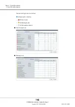
Reviews: