Dentsply Sirona CEREC Omnicam AC Service Manual Download Page 80

4 Repair
4.3 Replacing parts (without removing covers)

Dentsply Sirona

Service Manual CEREC Primescan AC, Primescan AC, CEREC Omnicam AC, Omnicam AC

80

66 81 832 D3696

D3696.076.01.02.02    05.2019
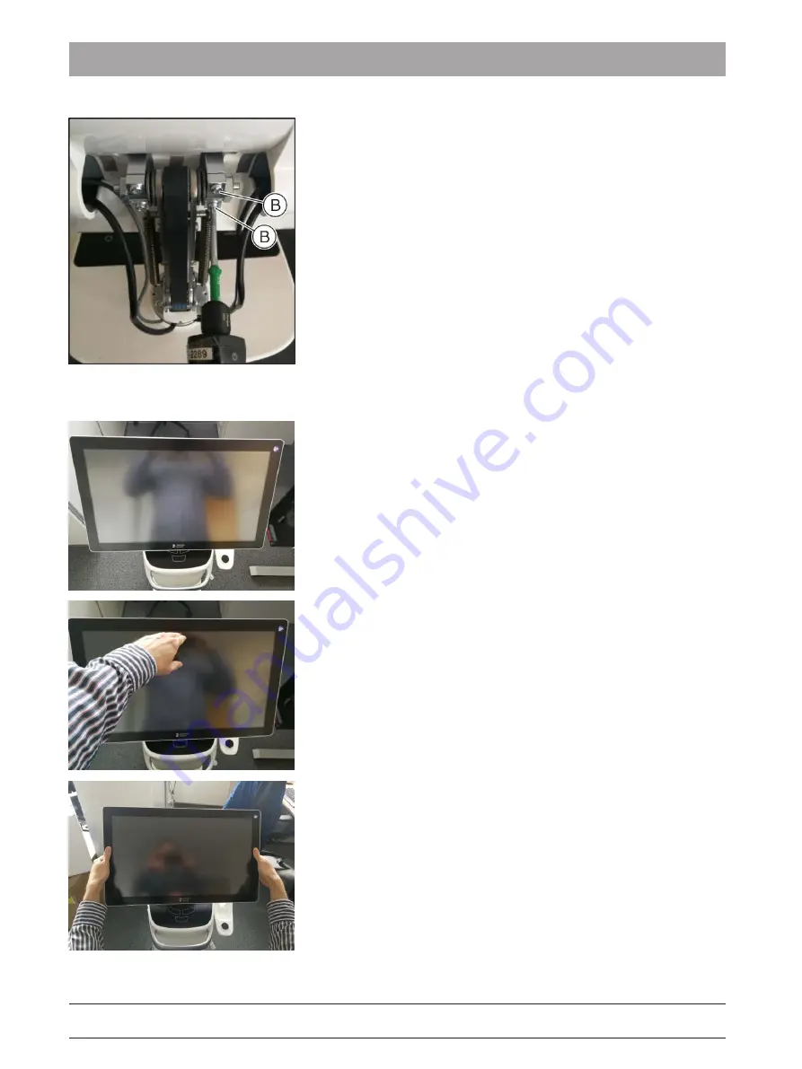
7.

Retighten the 2 screws (B, M4 X 35) with 2.5 Nm.

4.3.2.1.5

Check tightness

Check the tightness of the monitor by carrying out the following tests:

● Test 1: The monitor cannot lower itself in any position.

● Test 2: The monitor cannot be lowered in any position by pressing

with the fingers.

● Test 3: The monitor must be capable of being tilted using both hands

(left and right of monitor) without using high levels of force.

Summary of Contents for CEREC Omnicam AC

Page 1: ...New as of 05 2019 CEREC Primescan AC Primescan AC CEREC Omnicam AC Omnicam AC Service Manual English ...

Page 2: ...0 1 4 7 Measurements 10 1 4 8 Important instructions after repair maintenance 11 1 4 9 Safety labels 11 1 4 10 Wireless phone interference with equipment 13 1 4 11 Integration in a network or connection to a modem 13 1 4 12 Disposal 14 1 5 Technical data 15 1 6 PC overview 17 1 6 1 CEREC Primescan AC Primescan AC components 17 1 6 2 CEREC Omnicam AC Omnicam AC components 18 1 6 3 Overview of the c...

Page 3: ...5 3 3 2 CEREC Omnicam Omnicam 46 3 3 2 1 Scanner test and diagnostics for CEREC Omnicam Omnicam 46 4 Repair 50 4 1 General information on assembly 50 4 2 Removing covers and holders 51 4 2 1 Removing and installing covers 51 4 2 1 1 Cover overview 51 4 2 1 2 Opening the service cover 52 4 2 1 3 Closing the service cover 52 4 2 1 4 Left cover 52 4 2 1 5 Right cover 54 4 2 1 6 Front cover 55 4 2 1 7...

Page 4: ...104 4 3 2 11 Replacing the interface card 104 4 3 2 12 Replace the graphic card 105 4 3 2 13 Closing the PC 107 4 4 Replacing parts whereby the removal of covers is necessary 108 4 4 1 Replace internal scanner cable 108 4 4 2 Completely replacing the power input 108 4 4 3 Replacing the fan 111 4 4 4 Replacing the fan power pack 112 4 4 5 Replacing the radio module 113 4 4 6 Replacing the footswitc...

Page 5: ... 2019 5 8 Re test 131 8 1 When is the re test carried out 131 8 2 Description of device type 131 8 3 To be carried out on completion of the test 131 8 4 What the test steps involve 131 8 4 1 Visual inspection 131 8 4 2 Protective ground wire resistance 132 8 4 3 Device leakage current 132 8 4 4 Insulation resistance 132 8 4 5 Functional test 133 ...

Page 6: ... in the following ranges Rated line voltage 100 240V 50 60Hz Nominal current 5 0 2 1A Wireless phone interference with medical electrical equipment NOTE To ensure safe operation of medical electrical equipment the use of mobile wireless phones in practice or hospital environments is prohibited Disposal Observe the information on disposal in the relevant operating instructions Installation site Obs...

Page 7: ...rts catalog Order no Spares drive 63 21 868 Documents Operating the MC XL via LAN 61 90 503 CEREC Radio Module Operating Instructions 65 45 177 Service tools DrOmni Omnicam diagnostics program DrPrimescan Primescan diagnostics program Dentsply Sirona Restore Solution Tools Torx screwdriver sizes 06 10 20 30 20 250 mm long Torx screwdriver size 20 torque 2 5Nm for M4 x 35 screws Phillips screwdrive...

Page 8: ...ld result in serious bodily injury or death CAUTION A possibly dangerous situation that could result in slight bodily injury NOTE A possibly harmful situation which could lead to damage of the product or an object in its environment IMPORTANT Application instructions and other important information Tip Information for simplifying work 1 3 2 Formats and symbols used The formats and symbols used in ...

Page 9: ... accessories 1 4 3 Electrostatic discharge ESD warning label CAUTION Risk of injury or damage to components from electrostatic discharge For electrical components labeled with an ESD warning label observe the following instructions Apply the ESD protective measures Do not touch connector pins or sockets without applying ESD protective measures first Do not establish any connections between these c...

Page 10: ...r replacing parts Turn the device off Disconnect the power plug 1 4 6 Replacing parts WARNING Potentially lethal shock hazard when working near the power supply unit Disconnect from the line power supply Check for zero potential Switch the device off and disconnect the power plug before replacing parts The item numbers for ordering spare parts can be found in the spare parts catalog on the combi s...

Page 11: ...g checks must be performed after repair maintenance Any connections that may have loosened during repair must be reconnected This applies in particular to lines for the power supply and for the protective earth conductor The protective earth conductor resistor must be checked after attaching the covers R 100mΩ between components connected to the protective earth conductor and the protective earth ...

Page 12: ...ecting external interfaces In order to maintain electrical safety the rear covers of the acquisition unit must be kept closed while it is in operation service cover and cover on the monitor Do not touch the pins of the connectors When using the unit on the patient please note that the covers on the rear side of the unit service cover and cover on the monitor must remain closed and voltage sources ...

Page 13: ...it to a modem Network The acquisition unit may be operated in a network only if it is connected to a HUB switch The hub switch must be located in the room where the acquisition unit is operated permanently installed be grounded via an additional ground wire Cross section of the protective ground wire laid protected 2 5mm 2 laid unprotected 4mm 2 Modem At least one of the following specifications m...

Page 14: ...rding old electrical and electronic devices please be advised that such items must be disposed of in a special way within the European Union EU These regulations require environmental friendly usage disposal of old electrical and electronic devices Such items must not be disposed of as domestic refuse This has been expressed using the icon of the crossed out trash can since March 24 2006 amongst o...

Page 15: ...against ingress of water Ordinary device without protection against ingress of water Degree of contamination 2 Installation category Ⅱ Operating mode Continuous operation Transportation and storage conditions In the original transport packaging the acquisition unit withstands the following environmental conditions during transport and storage Temperature 25 C to 60 C 13 F to 140 F Relative humidit...

Page 16: ...EC Omnicam AC Omnicam AC 16 66 81 832 D3696 D3696 076 01 02 02 05 2019 Dimensions and weight Dimensions W x H x D in mm in inches 408 537 x 1190 x 443 16 06 21 14 x 46 85 x 17 44 Weight Total weight approx without monitor and battery approx without battery approx 38 kg 83 8 lbs 31 kg 68 3 lbs 36 kg 79 3 lbs ...

Page 17: ...1P7 MSI Z370 PC PRO MS 7B49 V1 0 BIOS version 1P7 Processor intel i7 8700 intel i7 8700 Memory 4 x 8 GB DDR4 2400 RAM 4 x 8 GB DDR4 2400 RAM SSD module 960 EVO 250GB 960 EVO 250GB Hard disk Seagate ST2000LX001 Seagate ST2000LX001 Graphics card RADEON RX 570 8GB various manufacturers RADEON RX 570 8GB various manufacturers Supply board Interface card QCC FBG 3 E3 6634245 Interface card QCC FBG 3 E3...

Page 18: ...370 PC PRO MS 7B49 V1 0 BIOS version 1P7 Processor intel i7 8700 intel i7 8700 Memory 4 x 8 GB DDR4 2400 RAM 4 x 8 GB DDR4 2400 RAM SSD module 960 EVO 250GB 960 EVO 250GB Hard disk Seagate ST2000LX001 Seagate ST2000LX001 Graphics card RADEON RX 570 8GB various manufacturers RADEON RX 570 8GB various manufacturers Supply board Interface card OC FBG 2 E2 6634229 Interface card OC FBG 2 E2 6634229 So...

Page 19: ...C Omnicam AC 1 General information 1 6 PC overview 66 81 832 D3696 D3696 076 01 02 02 05 2019 19 1 6 3 Overview of the connections on the PC A L4 monitor 12V B L7 2x or 3x WLAN antenna C L1 trackball touchpad D L2 E L3 2 scanner F L5 monitor signal HDMI G Fan 1 top H Fan 2 bottom ...

Page 20: ...C Omnicam AC 20 66 81 832 D3696 D3696 076 01 02 02 05 2019 I Fan 3 storage battery J L6 monitor USB K L9 radio modules LAN L L8 radio modules USB M L12 trackball touchpad USB IMPORTANT The position number and precise layout of the ports for the graphics card and mainboard may differ depending on the hardware version ...

Page 21: ...ntsply Sirona TeamViewer Quicksupport is preinstalled No Internet connection is required for this ü Internet connection is available 1 Start the program by opening the Dentsply Sirona folder in the start menu and then selecting TeamViewer Quicksupport 2 If necessary confirm any queries from the Windows user account control system that appear with Yes and report the ID and password displayed in the...

Page 22: ...eset the acquisition unit radio module via software Please note that a controlled pairing requires that the radio module to be paired is also reset Reset radio module ü The LAN cable for the radio module is plugged in 1 Start the OTC bat tool The program is preinstalled on the acquisition unit and can be found at C DentsplySirona Tools BM Radio 2 Connect with the installed radio module by activati...

Page 23: ... started in the final step Two additional windows are opened for this purpose For this step the camera should be held on an even surface which is as white as possible Above all it should be a non reflective surface One of the two windows contains the reference image the usual live image from CEREC and the other one displays a beam intensity pattern with grid pattern The white balance and brightnes...

Page 24: ...edure Uninstall the GenICam v2 1 and mvBlueCOUGAR x64 programs via the Windows settings before reinstalling driver version 1 12 50 The driver is located in the directory C DentsplySirona Drivers Matrix Vision The program itself also offers information about further problem cases Figures Figure 1 The program running normally in the console Figure 2 Reference image with clear green cast and reflex ...

Page 25: ...e Manual CEREC Primescan AC Primescan AC CEREC Omnicam AC Omnicam AC 2 Service tools 2 3 DrOmni Omnicam diagnostics program 66 81 832 D3696 D3696 076 01 02 02 05 2019 25 Figure 3 Strip image with clear green cast and reflex ...

Page 26: ...ndow opens with information regarding the program version and the date this version was created Subsequently the program searches for a connected Primescan scanner As soon as this search is successful a corresponding note is displayed and the scanner is accessed The ID for the camera electronics is then displayed and the camera is started If the DrPrimescan program finds firmware FW on the Primesc...

Page 27: ...ssessing the images Figure 2 shows how the images could look with the two live images Here a slight color deviation and the edge of the field of vision can be identified in the left image both effects are completely normal in the raw data of the camera and say nothing about the quality Nevertheless in this step it is possible and important to verify that both images are being transmitted smoothly ...

Page 28: ...ith each CEREC version users are advised to reinstall the CEREC software in this case No scanner is found Possible causes are as follows The camera is not connected or there is a fault with the cable and or the plug connection There is an error with the firmware In this event the following device Cypress FX3 Bootloader is displayed in the device manager If this is the case launch CEREC and switch ...

Page 29: ...re Solution 66 81 832 D3696 D3696 076 01 02 02 05 2019 29 2 5 Dentsply Sirona Restore Solution 2 5 1 Objective The objective of inserting the Restore Solution is to restore the software factory defaults as a means of rectifying faults for example after a system crash non physical hard disk malfunctions faulty software installations ...

Page 30: ...Omnicam AC 30 66 81 832 D3696 D3696 076 01 02 02 05 2019 2 5 2 Compatible PCs Dentsply Sirona Restore Solution is compatible with the PCs of the following devices CEREC Primescan AC Primescan AC CEREC Omnicam AC Omnicam AC inLab PC V5 x CEREC AC with CEREC Omnicam CEREC AC Connect with CEREC Omnicam CEREC AF AI AF Connect AI Connect ...

Page 31: ...gnized by BIOS and have no physical malfunctions There must be no changes made to the partitions on the hard disk 2 5 4 When can the procedure not be used This procedure is not suited for the initial configuring of a new hard disk Do not start the process if the following occurs System initialization or BIOS error messages are displayed The monitor display is not present Trackball or touchpad of t...

Page 32: ...t rather starts the installed Windows operating system conned a keyboard to the device and proceed with section Systems with a separate physical keyboard 32 2 5 6 3 Systems with a separate physical keyboard For systems featuring a separate physical keyboard 1 After switching on or performing a restart press the key which opens the boot menu repeatedly until the menu is displayed on the PC This is ...

Page 33: ...dates must also be installed 2 If the device is subsequently to be operated offline establish a short term Internet connection e g using a mobile telephone system Then open the Windows settings in the Start menu and click on Update and Security then Activation on the left Activation can be initiated here manually 3 Install the required software CEREC SW inLab SW etc 4 Check the interface parameter...

Page 34: ...imum results the scanner must be allowed to warm up for 2 minutes before calibration Recalibrate the scanner in the following cases following transport shaking stress or during first commissioning after storage in unheated or un air conditioned rooms temperature differences exceeding 30 C 85 F with temperature differences of over 15 C 60 F between the last calibration and operation In general carr...

Page 35: ...w is fully screwed in a clockwise motion until it gently locks into place 4 Click on the OK button Ä The measuring process starts Ä The software prompts you to proceed to the next latching 5 Turn the screw counter clockwise until you reach the next latching point 6 Click on the OK button Hold the CEREC Primescan Primescan CEREC Omnicam Omnicam scanner still Ä The software confirms the calibration ...

Page 36: ...tinued Ä Once the calibration is complete a message is displayed indicating this 3 Confirm the message by clicking the OK button Ä The CEREC Primescan Primescan CEREC Omnicam Omnicam scanner is calibrated Error message during calibration The software indicates if an error occurs during calibration If the calibration process resulted in errors restart the process End calibration ü The software indi...

Page 37: ...ou will achieve the best results if the scanner is color calibrated immediately before scanning a new case Carry out a color calibration also after changing a sleeve Heavily scratched sleeve window may not be used for a color analysis Storing a color calibration set The color calibration set must be stored in its packaging in a dry place which is protected from light It must be used with a disinfe...

Page 38: ...d the scanner at more of an oblique angle in order to avoid any glaring light and to make it easier to scan the codes If the QR code is recognized the next Please mount color calibration set step appears This step of the QR code scan is skipped during the subsequent color calibration and the serial number of the color calibration set is thus displayed If this does not match the serial number print...

Page 39: ... replaced regularly Observe the following Please note that the color calibration set can only be used with CEREC 5 software 5 x or Connect SW 5 can only be kept for use for a maximum of 2 years You can find the expiry date at the bottom of the color calibration set container Previous storage may mean that the period for use has been reduced to less than 2 years can only be used for one year after ...

Page 40: ...extraoral intraoral is set G 6 The intraoral area to be measured is dry G 7 No CPU or memory intensive applications are running in the background G 8 Adequate disk space is available on the C system partition and the data partition configurable in CEREC and usually D respectively If less than 10GB is free on one of the partitions there may be drops in performance or errors in the user software Use...

Page 41: ...supply board is working L11 Replace supply board L15 Replace the scanner S3 2D image quality inadequate Tint Image too dark too bright L20 Setting the right exposure mode extraoral intraoral L6 3D calibration of the scanner L7 Color calibration of the scanner S4 Color impression of the 3D model inadequate Tint Image too dark too bright See S3 S5 The scanner is not recognized as a USB device with t...

Page 42: ...eck install graphic card driver L9 Restore process L13 Replace the power supply unit S10 Scanner window sleeve window fogged up scan ner heater function broken Maintain heat up time 5 min L2 Disconnect PC from the power supply L1 Restart user software and or PC L15 Replace scanner S11 Visible damage to the scanner CAUTION The safety of the scanner as a medical device is no longer ensured L15 Repla...

Page 43: ...rating console for approx 15 seconds until the blue light is no longer on and is instead dark 6 Wait for 10 seconds 7 Insert the storage battery connect the power cable and start the acquisition unit L3 Disconnect plug in scanner cable Terminate user software Disconnect the scanner from the acquisition unit NOTE Disconnect by pulling out the connector and do not pull on the cable Slide the moving ...

Page 44: ...s 2 Expand the USB Controller category and you should see the MHT Optic Research AG 3D Scanner entry there 3 Continue with S5 if the entry is not there L9 Restore process Follow the instructions provided in the Dentsply Sirona Restore Solution 29 section L10 Replace the external cable Follow the instructions provided in the Replacing the camera cable 65 section Replace the internal cable Follow th...

Page 45: ... 6634245 power supply failure for the scanner may occur due to a defective CEREC Primescan Primescan scanner or a fault with the camera cable A connected scanner will then no longer work For an initial check of this fault condition the supply voltages output by the QCC interface card to supply the scanner can be inspected 1 Open the service cover see Opening the service cover in the service manual...

Page 46: ...ware version must be installed Open License Manager check license Ä Software starts without error message acquisition phase is active G 2 Omnicam is properly connected to acquisition unit i e plug connection is OK G 3 The prescribed heating period 15 min is observed G 4 Omnicam heater function test via finger Omnicam is hot enough to prevent mirror sleeve from fogging up G 5 Mirror sleeve is clean...

Page 47: ...9 Restore process L 14 Replace Omnicam S5 Live image and 3D Preview are canceled following initially proper acquisition process L 2 Restart user software and or PC L 3 Disconnect plug in scanner cable L 6 Check install Omnicam software L 17 Check install graphic card driver L 9 Restore process L 10 Use PC Diagnostic Tool L 7 Replace external internal cable L 8 Replace supply board L 13 Replace PC ...

Page 48: ...s and IP addresses for both LAN connections to the factory settings The configuration of the WLAN is not changed Make sure that the CEREC Omnicam is connected Go to the directory C DentsplySirona Tools Omni cam Network and start the Configure cmd pro gram Check the outputs for possible error messages L5 Use DrOmni Omnicam diagnostics program A link to launch the program can be found in the Dentspl...

Page 49: ...e Replacing the PC including the power supply unit 94 section L13 Replace PC Follow the instructions provided in the Replacing the PC including the power supply unit 94 section L14 Replace Omnicam Contact the hotline L15 Check license Go to the License Manager and check whether the required license is listed in the status overview L16 Replacing the heater Follow the instructions provided in the Re...

Page 50: ...ed Switch off the unit prior to beginning work Pull out the power cable NOTE Accessories For reasons of product safety this product may be operated only with original Dentsply Sirona accessories or third party accessories expressly approved by Dentsply Sirona The user is responsible for any damage resulting from the use of non approved accessories NOTE If cable is kinked or twisted Kinking or twis...

Page 51: ...air 4 2 Removing covers and holders 66 81 832 D3696 D3696 076 01 02 02 05 2019 51 4 2 Removing covers and holders 4 2 1 Removing and installing covers 4 2 1 1 Cover overview A Front cover panels B Cover left C Service cover D Service cover turning bolt E Power cable holder F Cover right G Grommet ...

Page 52: ...se up to the stop The slot of the turning bolt must be in a vertical position in an opened state 2 Press down the service cover as far as it will go and remove it 4 2 1 3 Closing the service cover 1 Put the service cover back in position and push it up as far as it will go 2 Turn the turning bolt with a screwdriver 5 or another suitable implement a coin or suchlike approx 90 clockwise up to the st...

Page 53: ...can AC CEREC Omnicam AC Omnicam AC 4 Repair 4 2 Removing covers and holders 66 81 832 D3696 D3696 076 01 02 02 05 2019 53 2 Flip the footswitch down 3 Unscrew the left screw B 4 Remove the left cover by pulling it out downwards slightly and then to the rear ...

Page 54: ... Dentsply Sirona Service Manual CEREC Primescan AC Primescan AC CEREC Omnicam AC Omnicam AC 54 66 81 832 D3696 D3696 076 01 02 02 05 2019 4 2 1 5 Right cover 1 Unscrew the 3 screws A TX20 2 Flip the footswitch down 3 Unscrew the right screw B ...

Page 55: ...02 05 2019 55 4 Remove the right cover by pulling it out downwards slightly and then to the rear 4 2 1 6 Front cover IMPORTANT First remove scanner holder or handle In order for the front cover to be able to be removed the scanner holder must first be removed Alternatively the front handle can be removed beforehand then the scanner holder can stay in its position ...

Page 56: ...Removing covers and holders Dentsply Sirona Service Manual CEREC Primescan AC Primescan AC CEREC Omnicam AC Omnicam AC 56 66 81 832 D3696 D3696 076 01 02 02 05 2019 1 Unscrew the 3 screws A 2 Unscrew the 3 screws B ...

Page 57: ...rwards and out 4 2 1 7 Replacing the kinematics cover 1 Unscrew 2 screws and remove cover bearing flange 2 Unscrew 4 screws and remove bottom arm cover 3 Unscrew 2 screws from cable fixings and remove 4 Remove front arm cover it may be necessary to move the kinematics a little to do so 5 Unscrew 2 screws and remove monitor bearing cover 6 Reassembling everything in reverse order when doing so note...

Page 58: ...over parts set B CEREC Primescan Primes can scanner holder C CEREC Primescan Primescan internal scan ner cable ü The service cover is open see Opening the service cover 52 ü The right cover is removed see Right cover 54 1 Detach the scanner connector from the scanner cable and set the scanner aside safely 2 Unscrew the 3 screws A from the device and remove the scanner holder laterally from the dev...

Page 59: ...nicam internal scanner cable ü The service cover is open see Opening the service cover 52 ü The right cover is removed see Right cover 54 1 Unscrew the scanner from the scanner cable and set the scanner aside safely 2 Unscrew the 3 screws A from the device and remove the scanner holder laterally from the device When doing so detach the connector of the heater cable 3 Insert the new scanner holder ...

Page 60: ... 2 3 1 Replacing the heater ü The scanner holder is removed see Replacing the CEREC Omnicam Omnicam scanner holder 59 1 Unscrew the cover parts set A 5 screws 2 Unscrew the heater C 3 screws 3 Fasten the new heater using 3 screws 4 Screw the cover parts set back on using 5 screws 5 Insert the scanner holder as described under Replacing the CEREC Omnicam Omnicam scanner holder 59 ...

Page 61: ... main fuse DANGER Potentially lethal shock hazard People can be injured or electrical components of the unit destroyed Switch off the unit prior to beginning work Pull out the power cable NOTE Fuse type Use only fuses of the same type in the fuse module A Main fuses C Window B Fuse module Fuses T8A H 250V Order No 62 33 188 ü The power plug must be disconnected 1 Unlatch the fuse module with a scr...

Page 62: ... The optimum switching point is reached when the clearance of an engaged but not actuated footswitch is approximately 6 7 mm 4 3 1 3 Replacing double castors 1 Remove the scanner from the holder and set it safely aside For a device with a trackball remove the trackball from the spherical recess 2 Carefully turn the device over onto a soft foam base onto the service cover In this process hold on to...

Page 63: ...ing the monitor USB cover 1 Open the monitor USB cover 2 Remove the monitor USB cover by using your left hand to bend the cover in the center from the inside to the outside slightly while at the same time using your right thumb to push the cover to the left out of the top pivot 3 Insert the new monitor USB cover diagonally into the bottom pivot and press to the right until it is locked in the top ...

Page 64: ... pulling it out diagonally out of the guide rail To do this lift the device up slightly and carefully at the front or turn it over onto a soft base onto the service cover In this process hold on to the monitor tightly so that it does not tilt to the side uncontrollably 4 First insert the new footswitch in position A diagonally 5 Then insert the footswitch on the left side diagonally in the rail an...

Page 65: ...amera cable IMPORTANT Perform the replacement of the camera cable in a dust free environment Primescan 1 Attach the tool A REF 6399229 to the cover nut B with the two pins 2 Release the cover nut B manually with the aid of the tool 3 Remove the cover nut B 4 Take the camera cover C off the camera 5 Remove the dust protection sticker D The sticker is no longer required and can be disposed of 6 Remo...

Page 66: ...camera 8 Carefully disconnect the USB connector G from the camera and remove the old camera cable 9 Detach the camera cover B from the old camera cable and push it over the new camera cable The old camera cable is no longer required and can be disposed of 10 Insert the USB connector G of the new camera cable into the USB socket of the camera Note The USB connector in the USB C Format can be insert...

Page 67: ...housing and fix it with the two screws tightening torque 30Ncm 13 Place the dust protection sticker D supplied in the package into the depicted position on the camera housing and stick it down firmly Make sure that the gap J between the camera housing and the strain relief cover is covered by the sticker 14 Attach the spacer E 15 Attach the camera cover C onto the camera 16 First turn the cover nu...

Page 68: ...th the two pins and turn it using a torque wrench tightening torque 2 5 Nm Omnicam 1 Attach the tool A REF 6399229 to the cover nut B with the two pins 2 Release the cover nut B manually with the aid of the tool 3 Remove the cover nut B 4 Take the camera cover C off the camera 5 Release the two screws and remove the strain relief cover D from the camera housing IMPORTANT Ensure that no dust partic...

Page 69: ...era cable and push it over the new camera cable in the order presented Pay attention to the correct alignment of the spacer as depicted in the illustration The old camera cable is no longer required and can be disposed of 8 Insert the connector E of the new camera cable into the socket of the camera 9 Place the hex G of the new camera cable with a flat side downwards onto the EMC adhesive pad H of...

Page 70: ...6 01 02 02 05 2019 11 Push the spacer F onto the camera housing Make sure that the thick part of the spacer is pointing downwards 12 Attach the camera cover C onto the camera 13 First turn the cover nut B manually onto the thread on the camera 14 Attach the tool A REF 6399229 to the cover nut B with the two pins and turn it using a torque wrench tightening torque 3 2 Nm ...

Page 71: ...from the scanner body 1 Hold the holding ring between your thumb and index finger Ä In doing so the O ring is clamped in 2 Use your thumb and index finger to guide towards the holding nut as shown above Ä During this process the O ring is partially pushed out of the groove and an arc forms 3 Use your other hand to touch the O ring on this arc and remove it Fitting the new O ring NOTE Do not damage...

Page 72: ...nd index finger to push the O ring into the groove in a similar way to pushing it out but without any force 3 Guide your thumb and index finger in such a way along the groove until the O ring is fully positioned in the groove NOTE The O ring can be damaged Ensure that the O ring fits in the groove without twisting in order to prevent damage to the O ring when fitting the sleeve IMPORTANT Replaceme...

Page 73: ... 02 05 2019 73 4 3 2 Replacing parts by removing the service cover 4 3 2 1 Replace the monitor kinematics Use the parts available in the 6720135 Kinematik ERS SET spare parts to replace the monitor kinematics 4 3 2 1 1 Removing the covers 1 Remove the monitor see Replacing the monitor 85 and place it on a soft and clean base as shown 2 Unscrew 2 screws A M3 X 6 Precote TX10 ...

Page 74: ...y Sirona Service Manual CEREC Primescan AC Primescan AC CEREC Omnicam AC Omnicam AC 74 66 81 832 D3696 D3696 076 01 02 02 05 2019 3 Remove the kinematics cover bearing flange 4 Pivot the entire monitor holder away from you and unscrew 4 PT screws B F 3 X 8 TX10 ...

Page 75: ...Omnicam AC 4 Repair 4 3 Replacing parts without removing covers 66 81 832 D3696 D3696 076 01 02 02 05 2019 75 5 Carefully pivot the monitor holder C in order to get past the kinematics bearing flange with the lever arm cover at the front D 6 Remove the lever arm cover at the front ...

Page 76: ...mescan AC CEREC Omnicam AC Omnicam AC 76 66 81 832 D3696 D3696 076 01 02 02 05 2019 7 Loosen 2 PT screws E F 3 X 8 and pivot the cable reliefs away 8 Remember the cable route take a photo or mark out the route so that you can lay the cable in the exact same way later 9 Remove the lever arm cover at the rear ...

Page 77: ...81 832 D3696 D3696 076 01 02 02 05 2019 77 10 Unscrew 2 screws F M3 X 6 Precote and remove the 2 monitor connection covers G 4 3 2 1 2 Remove the monitor kinematics 1 Remove the cable guard I 2 Carefully remove the 4 cables from the bearing flange starting with the smallest connectors 3 Unscrew the 4 screws H M4 X 35 TX20 and remove the kinematics ...

Page 78: ...arm cover temporarily on the uncovered kinematics in order to center this above the geometry for the lever arms 4 Set equal clearance to the left and right by moving the kinematics into the long holes of the bearing pedestals 5 Remove the lever arm cover at the rear once again 6 Screw the 4 screws H M4 X 35 in finger tight 7 Carefully guide the 4 cables through the bearing flange by starting with ...

Page 79: ...m away from the bearing pedestal 3 Apply Loctite carefully on the gear shaft between the M12 nuts and bearing pedestals 4 Screw the 2 M12 nuts back onto the bearing pedestal 5 Loosen the 2 screws B M4 X 35 Leave the other ones screwed in so that the centering does not change 6 Retighten one M12 nut A in a clockwise direction move wrench up Start with a 1 2 rotation Ä The disk springs are pressed t...

Page 80: ...ten the 2 screws B M4 X 35 with 2 5Nm 4 3 2 1 5 Check tightness Check the tightness of the monitor by carrying out the following tests Test 1 The monitor cannot lower itself in any position Test 2 The monitor cannot be lowered in any position by pressing with the fingers Test 3 The monitor must be capable of being tilted using both hands left and right of monitor without using high levels of force...

Page 81: ...ests is unsuccessful readjust the right and left sides in turn as described until the test is completed successfully 1 Loosen the 2 screws A M4 X 35 TX20 Leave the other ones screwed in so that the centering does not change 2 Retighten one M12 nut B SW19 open end wrench in a clockwise direction move wrench down Start with a 1 2 rotation Ä The disk springs are pressed together the tightness increas...

Page 82: ...and place it on a soft and clean base once again as shown 2 Insert the 2 monitor connection covers G and screw the 2 screws F M3 X 6 Precote on finger tight NOTE Do not tighten too hard as otherwise the plastic parts may burst 3 Insert the lever arm cover at the rear 4 Pivot the uncovered kinematics away from you against the cover and hold it there 5 Insert the cables into the guides K thin cable ...

Page 83: ...Do not tighten too hard as otherwise the screw bosses may burst 7 Carefully retighten the cables These must run above each other under the cable guard and may only be pressed slightly by the cover 8 Insert the lever arm cover at the front 9 Carefully pivot the monitor holder C in order to get past the kinematics bearing flange with the lever arm cover at the front D NOTE Cables may become crushed ...

Page 84: ... Primescan AC CEREC Omnicam AC Omnicam AC 84 66 81 832 D3696 D3696 076 01 02 02 05 2019 10 Pivot the entire monitor holder away from you and screw the 4 PT screws B F 3 X 8 in finger tight NOTE Do not tighten too hard as otherwise the screw bosses may burst 11 Insert the kinematics cover bearing flange ...

Page 85: ... 2 screws A M3 X 6 Precote in tightly NOTE Do not tighten too hard as otherwise the plastic parts may burst 4 3 2 2 Replacing the monitor NOTE Risk of damage to the display caused by mechanical impact Do NOT subject active display area to any mechanical pressure NEVER touch active display area with sharp or pointed objects Removing the monitor 1 Open the service cover see Opening the service cover...

Page 86: ... AC 86 66 81 832 D3696 D3696 076 01 02 02 05 2019 2 Loosen and remove the monitor brake 2 screws 3 Unscrew the locking plate mini DIN connector 1 screw A 4 Detach the three cables that run from the monitor to the PC from the PC and unscrew the ground cable 5 Release the monitor cables from the clips 6 Remove the monitor in an upward motion ...

Page 87: ...s 66 81 832 D3696 D3696 076 01 02 02 05 2019 87 Installing the monitor 1 Guide the 4 monitor cables through the opening and insert the monitor 2 Route the 4 monitor cables as follows HDMI cable and USB cable on the right ground cable and cable L4 with mini DIN connector on the left 3 Screw the monitor brake on again as shown with the 2 screws ...

Page 88: ...8 66 81 832 D3696 D3696 076 01 02 02 05 2019 4 Insert the eyelet of the ground cable L14 as shown between the screw head and tooth washer Fasten the ground cable using the screw 5 Route the cable L4 behind the handle and insert the mini DIN connector into the socket X101 of the supply board 6 Insert the USB connector 7 Insert the HDMI connector ...

Page 89: ... 2019 89 8 Re tighten the locking plate mini DIN connector with 1 screw A 9 Route the cables as shown and clip them into the holders 10 Close the service cover see Closing the service cover 52 4 3 2 3 Control unit 4 3 2 3 1 Removing and inserting the control unit Removal ü The monitor is removed see Replacing the monitor 85 1 Unscrew the fastening screws A from the locking plates ...

Page 90: ...rewdriver as a lever and push the locking plate back up to the stop 4 Remove the trackball if the configuration provides for it and set it safely aside 5 Raise the complete control unit upwards slightly and carefully 6 Detach the USB connector and the connector of cable L1 7 Remove the control unit Installation NOTE When performing the following installation steps make sure that all plug connectio...

Page 91: ...e gap A must be open as shown 4 Install the control unit If the control unit gets stuck or is difficult to move once inserted into the frame correct the position of the plates screwed onto the control unit 5 Push the left locking plate forwards up to the stop and then screw it back on again with the screw Perhaps help things along by simultaneously pressing the control unit downwards slightly on t...

Page 92: ...ete control unit carefully upwards slightly see Removing and inserting the control unit 89 2 Disconnect the plug connections of the control unit cable A and remove the control unit cable NOTE When performing the following installation steps make sure that all plug connections snap in place correctly 3 Route the new control unit cable A and re establish the plug connections 4 Attach the control uni...

Page 93: ...mplete control unit carefully upwards slightly see Removing and inserting the control unit 89 2 Disconnect the plug connections of the interface cable A and remove the interface cable NOTE When performing the following installation steps make sure that all plug connections snap in place correctly 3 Route the new interface cable B and re establish the plug connections 4 Attach the control unit and ...

Page 94: ...mnicam AC 94 66 81 832 D3696 D3696 076 01 02 02 05 2019 4 3 2 4 Replacing the PC including the power supply unit Removal 1 Open the service cover see Opening the service cover 52 2 If the option is available remove the battery see Replace battery optional 100 3 Unscrew the partition plate 2 screws 4 Remove the partition plate as shown ...

Page 95: ... 81 832 D3696 D3696 076 01 02 02 05 2019 95 5 Unscrew the locking plate mini DIN connector 1 screw A 6 Remove all connectors from the PC 7 Unscrew the 3 screws A 8 Pull out the PC by the handle up to the safety stop When doing so check the fan cables 9 Raise the PC up slightly to remove it from the housing and pull it out carefully and completely ...

Page 96: ...ear side of the power supply unit Installation 1 Insert the connector of the power supply into the socket of the rear side of the power supply unit 2 Hang the PC in the track intended for this purpose NOTE Cables can be damaged Pay attention to the cables when inserting and moving the PC The cables must never become kinked or jammed 3 Push the PC completely into the acquisition unit 4 Fasten the P...

Page 97: ... 076 01 02 02 05 2019 97 5 Insert all connectors as shown for connector assignment see Overview of the connections on the PC 19 Note the information in Replacing the WLAN card 104 if necessary for the WLAN antennae 6 Route the cables and clip them into the holders 7 Re tighten the locking plate mini DIN connector with 1 screw A 8 Install the locking plate as shown ...

Page 98: ...l 100 11 Close the service cover see Closing the service cover 52 4 3 2 4 1 Replace PC power supply ü The PC is removed see Replacing the PC including the power supply unit 94 1 Turn the PC on its side 2 Remove the 2 fastening screws 3 Pull out the power supply unit out of the guide tabs In doing so make sure the foam rubber strip A does not become damaged 4 Disconnect the 4 plug connections and d...

Page 99: ...placing parts without removing covers 66 81 832 D3696 D3696 076 01 02 02 05 2019 99 6 Plug the new power supply unit into the guide tabs Make sure that the foam rubber strip A is not dislocated through the insertion of the power supply unit 7 Screw the power supply unit on tight with the 2 fastening screws ...

Page 100: ...r see Opening the service cover 52 2 Remove the 2 fastening screws C cross head screws 3 Remove the storage battery 4 Slide in the new storage battery using the guide rails and guide pins up to the stop NOTE Risk of fault during operation and defects to the system If the storage battery is not screwed down faults during operation and defects to the system may occur Always screw the storage battery...

Page 101: ...he service cover 52 2 Detach the DVD drive connector 3 Unscrew the 3 fastening screws and pull out the DVD drive with the retaining plate 4 Detach the three M2 screws and remove the DVD drive from the retaining plate 5 Install the new DVD drive in the retaining plate 6 Slide in the new DVD drive using the guide rails up to the stop and screw it in place with the 3 fastening screws 7 Attach the DVD...

Page 102: ...e PC including the power supply unit 94 1 Turn the PC onto its side as shown 2 Unscrew the 3 screws A 3 Push the cover forwards approximately 2 cm In this process the seal will tear 4 Lift up the cover on the right side slightly and pull it out to the right 4 3 2 8 Replacing the SSD module 1 Open the PC see Opening the PC 102 2 Unscrew the fastening screw Ä The SSD module springs upwards on the ri...

Page 103: ...ush it downwards on the right side 5 Screw the SSD module down tightly with the fastening screw 6 Close the PC see Closing the PC 107 4 3 2 9 Replacing the hard drive 1 Open the PC see Opening the PC 102 2 Unscrew the 4 screws from the rear side 3 Detach the 2 connectors 4 Attach the 2 connectors to the new hard drive 5 Screw the new hard disk down onto the rear side with the 4 screws 6 Close the ...

Page 104: ...e Closing the PC 107 Note on connecting the WLAN antennae The WLAN card may have two or three antenna ports If three antennae are installed in the acquisition unit but the WLAN card only has two ports connect one antenna from each side of the acquisition unit For this use the antenna closest to the PC ports on the side that has two antennae Next secure the antenna cable for the third antenna not i...

Page 105: ... the lock for the 3 black connectors first 4 Attach the 4 connectors to the new interface card 5 Insert the new interface card into the slot 6 Fasten the slot plate with a screw 7 Close the PC see Closing the PC 107 4 3 2 12 Replace the graphic card 1 Open the PC see Opening the PC 102 2 Unscrew the 2 screws A 3 Lift up the attachment bracket and swing it to the side 4 Press the connector lock and...

Page 106: ... 81 832 D3696 D3696 076 01 02 02 05 2019 6 Press the socket lock downwards 7 Pull the graphics card up and out of the PC 8 Insert the new graphics card into the slot and lock it 9 Fasten the slot plate with 2 screws 10 Insert the connector until it latches 11 Screw the attachment bracket back on with 2 screws A 12 Close the PC see Closing the PC 107 ...

Page 107: ... removing covers 66 81 832 D3696 D3696 076 01 02 02 05 2019 107 4 3 2 13 Closing the PC 1 Insert the cover so that a gap of roughly 2 cm is kept at the rear Then tilt the cover down 2 Then slide the cover backwards up to the stop 3 Screw down the cover using 3 screws A 4 Attach the technician s conformity seal provided as shown ...

Page 108: ...1 Detach the scanner connector from the scanner cable and set the scanner aside safely 2 Remove the front cover see Front cover 55 3 Loosen the 2 screws A and remove the cable connector B 4 Loosen the internal scanner cable B from the clips and remove it 5 Lay the new internal scanner cable B as shown and clip it into the holders 6 Reinstall the front cover 4 4 2 Completely replacing the power inp...

Page 109: ... AC 4 Repair 4 4 Replacing parts whereby the removal of covers is necessary 66 81 832 D3696 D3696 076 01 02 02 05 2019 109 1 Detach the connector B from the power plug but leave it in the device 2 Unscrew the screw of the plate cover 3 Lift up the plate cover at the bottom and take it out ...

Page 110: ...icam AC Omnicam AC 110 66 81 832 D3696 D3696 076 01 02 02 05 2019 4 Pull both cable lugs off with needle nosed pliers 5 Unscrew the 2 screws A and remove the power input 6 Insert the new power input and screw it tight with the 2 screws A 7 Attach both cable lugs with needle nosed pliers 8 Insert the plate cover at the top and tilt it downwards ...

Page 111: ...alling covers 51 13 Plug in the power plug again 4 4 3 Replacing the fan ü The cover is detached see Removing and installing covers 51 ü The PC is removed see Replacing the PC including the power supply unit 94 1 Pull the fan sleeve with fan inwards and out 2 Remove the defective fan from the fan sleeve and insert the new fan into the sleeve 3 Insert the 4 knobs of the fan sleeve into the holes an...

Page 112: ...e PC including the power supply unit 94 1 Pull the 4 fastening pins inwards and out and detach the fan 2 Hold the new fan over the fan opening 3 Pull the 4 supplied fastening pins into the holes on the chassis and on the fan until the heads are on the inside of the chassis 4 Route the cables through the opening into the chassis interior 5 Shorten the 4 fastening pins so that around 10 mm protrude ...

Page 113: ...le L8 from the radio module 2 Detach the connector of the data cable L9 from the radio module 3 Open the Velcro fastener and remove the radio module 4 Place the new radio module into the retaining plate and fix it with Velcro fastener 5 Plug the USB connector of the cable L8 into the radio module 6 Plug the connector of the data cable L9 into the radio module 7 Reinstall the covers see Removing an...

Page 114: ...Insert the new footswitch cable and attach the connector 4 Screw the switch back on with 2 screws 5 Adjust the footswitch s switching point with the adjusting screw see Adjusting the footswitch 62 6 Reinstall the covers see Removing and installing covers 51 4 4 7 Replace the handle ü The control unit is removed see Removing and inserting the control unit 89 1 Remove the four screws and then take o...

Page 115: ...justments 5 1 Set the monitor kinematics 66 81 832 D3696 D3696 076 01 02 02 05 2019 115 5 Settings and adjustments 5 1 Set the monitor kinematics 5 1 1 Removing the covers 1 Remove the monitor see Replacing the monitor 85 and place it on a soft and clean base as shown 2 Unscrew 2 screws A M3 X 6 Precote TX10 ...

Page 116: ...ply Sirona Service Manual CEREC Primescan AC Primescan AC CEREC Omnicam AC Omnicam AC 116 66 81 832 D3696 D3696 076 01 02 02 05 2019 3 Remove the kinematics cover bearing flange 4 Pivot the entire monitor holder away from you and unscrew 4 PT screws B F 3 X 8 TX10 ...

Page 117: ...icam AC 5 Settings and adjustments 5 1 Set the monitor kinematics 66 81 832 D3696 D3696 076 01 02 02 05 2019 117 5 Carefully pivot the monitor holder C in order to get past the kinematics bearing flange with the lever arm cover at the front D 6 Remove the lever arm cover at the front ...

Page 118: ...rimescan AC CEREC Omnicam AC Omnicam AC 118 66 81 832 D3696 D3696 076 01 02 02 05 2019 7 Loosen 2 PT screws E F 3 X 8 and pivot the cable reliefs away 8 Remember the cable route take a photo or mark out the route so that you can lay the cable in the exact same way later 9 Remove the lever arm cover at the rear ...

Page 119: ...e monitor kinematics 66 81 832 D3696 D3696 076 01 02 02 05 2019 119 10 Unscrew 2 screws F M3 X 6 Precote and remove the 2 monitor connection covers G 5 1 2 Adjust the monitor kinematics 1 Guide the 4 monitor cables through the sleeve bearing and insert the monitor into the acquisition unit without any cover on the monitor holder ...

Page 120: ...them away from the bearing pedestal 3 Apply Loctite carefully on the gear shaft between the M12 nuts and bearing pedestals 4 Screw the 2 M12 nuts back onto the bearing pedestal 5 Loosen the 2 screws B M4 X 35 Leave the other ones screwed in so that the centering does not change 6 Retighten one M12 nut A in a clockwise direction move wrench up Start with a 1 2 rotation Ä The disk springs are presse...

Page 121: ...etighten the 2 screws B M4 X 35 with 2 5Nm 5 1 3 Check tightness Check the tightness of the monitor by carrying out the following tests Test 1 The monitor cannot lower itself in any position Test 2 The monitor cannot be lowered in any position by pressing with the fingers Test 3 The monitor must be capable of being tilted using both hands left and right of monitor without using high levels of forc...

Page 122: ...tests is unsuccessful readjust the right and left sides in turn as described until the test is completed successfully 1 Loosen the 2 screws A M4 X 35 TX20 Leave the other ones screwed in so that the centering does not change 2 Retighten one M12 nut B SW19 open end wrench in a clockwise direction move wrench down Start with a 1 2 rotation Ä The disk springs are pressed together the tightness increa...

Page 123: ...5 1 5 Reattach the covers 1 Remove the monitor and place it on a soft and clean base once again as shown 2 Insert the 2 monitor connection covers G and screw the 2 screws F M3 X 6 Precote on finger tight NOTE Do not tighten too hard as otherwise the plastic parts may burst 3 Insert the lever arm cover at the rear 4 Pivot the uncovered kinematics away from you against the cover and hold it there ...

Page 124: ...to the guides K thin cable first Ensure that the radius is adequate L 6 Pivot the cable reliefs above the cables and screw these in with the 2 PT screws E F 3 X 8 finger tight NOTE Do not tighten too hard as otherwise the screw bosses may burst 7 Carefully retighten the cables These must run above each other under the cable guard and may only be pressed slightly by the cover 8 Insert the lever arm...

Page 125: ...the monitor holder C in order to get past the kinematics bearing flange with the lever arm cover at the front D NOTE Cables may become crushed Ensure that the lever arm covers fit into each other perfectly and that no cables are caught in between 10 Pivot the entire monitor holder away from you and screw the 4 PT screws B F 3 X 8 in finger tight NOTE Do not tighten too hard as otherwise the screw ...

Page 126: ...e Manual CEREC Primescan AC Primescan AC CEREC Omnicam AC Omnicam AC 126 66 81 832 D3696 D3696 076 01 02 02 05 2019 11 Insert the kinematics cover bearing flange 12 Screw the 2 screws A M3 X 6 Precote in tightly NOTE Do not tighten too hard as otherwise the plastic parts may burst ...

Page 127: ...C including the power supply unit 94 Clean the PC fans using suction from the inside 6 2 Replacing cleaning the filter NOTE Maintenance performed by trained technical personnel is recommended on at least an annual basis Maintenance should include the filter mat the filter made from metal grating mesh and the storage battery 1 Flip the footswitch down 2 Pull out the filter 3 Place a new filter on t...

Page 128: ...AC CEREC Omnicam AC Omnicam AC 128 66 81 832 D3696 D3696 076 01 02 02 05 2019 5 Open up the lengthways cover by pushing the lateral spring plate 6 Remove the metal grille and clean it e g with a vacuum cleaner 7 Insert the cleaned metal grille and close the cover shut until the lateral spring plate latches in ...

Page 129: ... Manual CEREC Primescan AC Primescan AC CEREC Omnicam AC Omnicam AC 7 Circuit diagrams 7 1 CEREC Primescan AC Primescan AC 66 81 832 D3696 D3696 076 01 02 02 05 2019 129 7 Circuit diagrams 7 1 CEREC Primescan AC Primescan AC ...

Page 130: ... diagrams 7 2 CEREC Omnicam AC Omnicam AC Dentsply Sirona Service Manual CEREC Primescan AC Primescan AC CEREC Omnicam AC Omnicam AC 130 66 81 832 D3696 D3696 076 01 02 02 05 2019 7 2 CEREC Omnicam AC Omnicam AC ...

Page 131: ...mnicam AC is a class I device with a detachable power supply cord The camera is a type BF applied part 8 3 To be carried out on completion of the test 1 Visual inspection 2 Protective ground wire resistance 3 Device leakage current 4 Insulation resistance 5 Functional test 8 4 What the test steps involve 8 4 1 Visual inspection Check that the device labels are present and legible Do the fuses inse...

Page 132: ...nel must be 200 mΩ The protective ground wire resistance from the power cable plug to the PC rear panel must be 300 mΩ 8 4 3 Device leakage current The device leakage current must be measured in relation to the PC rear panel In the case of direct measurement under normal conditions it must be 0 1 mA In the case of a first fault protective ground wire disconnected it must be 0 5 mA 8 4 4 Insulation...

Page 133: ...tion piece suspended from the camera Ä The resulting image must not exhibit any surface defects The re test is now complete If any of the test criteria have not been met the acquisition unit CEREC Primescan AC Primescan AC CEREC Omnicam AC Omnicam AC must be repaired accordingly Record the completion of the test steps in the test report The test reports are recorded in a separate document in the r...

Page 134: ... be required due to technical improvements Sirona Dental Systems GmbH Sprache englisch Printed in Germany D3696 076 01 02 02 05 2019 Ä Nr 127 377 Sirona Dental Systems GmbH Fabrikstr 31 64625 Bensheim Germany www dentsplysirona com Order No 66 81 832 D3696 ...

Reviews: