Capintec CAPTUS 2000 Owner'S Manual Download Page 36

CAPINTEC, INC 

CAPTUS

®

 2000 


SYSTEM PARAMETERS


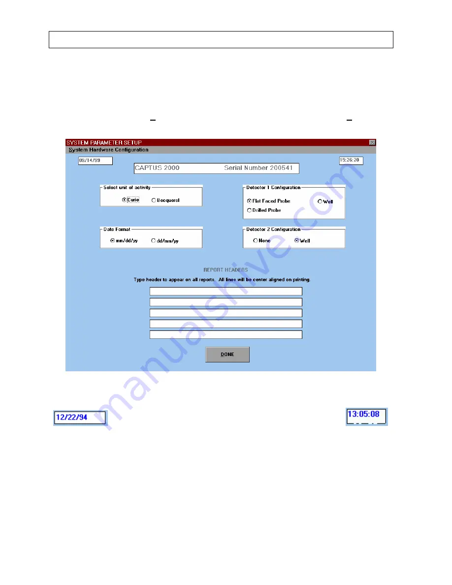
The System Parameters module displays the date, time, system serial number, units of 
activity, detector configuration, date format and report header.  To access information about 
system parameters, select 

Systems Parameters

... from the drop down list under 

Setup

.  

The system parameter setup screen will appear as shown in Figure 4-2. 


Figure 4-2 


Figure 4-3 


The date and time used in the CAPTUS

®

 2000 software are taken from the computer, and 

displayed throughout the system, Figure 4-3.  Note that the transition from 1999 to the year 
2000 will not be a problem with the CAPTUS

®

 2000 software because it utilizes a four digit 

year in its calculations. 
 
Reference the documentation which came with the computer for changing the date and time. 

4-4 

SYSTEM SETUP 

July 00 

Summary of Contents for CAPTUS 2000

Page 1: ...rrow Road Ramsey NJ 07446 Phone 800 ASK 4CRC Fax 201 825 1336 Capintec Inc Service Center 540 Alpha Drive Pittsburgh PA 15238 Phone 800 227 6832 Fax 412 963 0610 Copyright 1993 Capintec Inc CAPTUS is...

Page 2: ......

Page 3: ...uirements 2 3 Environment requirements 2 3 Operational 2 3 Storage 2 4 Isolation Transformer 2 4 Printer 2 4 Computer System Minimum System Requirements 2 4 MCA Interface PC Board Accuspec NaI Plus Bo...

Page 4: ...M SETUP Installation 4 1 Environment Requirements 4 1 Operational 4 1 Storage 4 1 Power Requirements 4 1 Turn On Procedure 4 2 General Operational Setup 4 3 System Parameters 4 4 Normal Values 4 7 Ref...

Page 5: ...ormation 6 15 Making Measurements 6 16 Predose Measurements 6 18 Capsule Count Measurement 6 20 Room Background Measurement 6 22 Patient Background Count 6 23 Patient Neck Count 6 24 Results 6 25 Prin...

Page 6: ...ting Patient Information 8 29 Making Measurements 8 30 Test Results 8 35 Printing Test Results 8 36 RBC Survival Test 8 38 Adding Patients 8 39 Editing Patient Information 8 41 Deleting Patient Inform...

Page 7: ...10 15 Time Activity Analysis 10 17 Setup Information 10 17 Making Measurements 10 19 Displaying Results 10 20 Save Time Activity Results 10 22 Recall Time Activity Results 10 22 Printing Results 10 23...

Page 8: ......

Page 9: ...hysics Inc an Amersham Company of Arlington Heights IL SYSTEM DESCRIPTION Your new CAPTUS 2000 is available in several configurations Please take a moment to review your system to determine exactly th...

Page 10: ...netic compatibility This equipment generates radio frequency energy and if not installed and used in accordance with the instructions may cause harmful interference to nearby devices However there is...

Page 11: ...or consultation at all times Precise compliance with the warnings and instructions is an essential condition for normal use correct application and thus safety of patients and user SYMBOL DEFINITIONS...

Page 12: ...efully swing upward and cause serious bodily injury to the operator The collimator is safely installed on the spring arm when the red warning ring is NOT visible between the collimator and the recepta...

Page 13: ...rements the voltage and serial number of the system and the replacement fuse values for both power line voltages Please refer to CHAPTER 11 CLEANING AND MAINTENANCE for instructions on how to change t...

Page 14: ...servicing to qualified personnel CAUTION No internal adjustments inside the Detector Computer or Printer that may be performed by the user within the conditions of the warranty except for changing the...

Page 15: ...result in order to minimize measurement errors NOTE It is recommended that periodic every five years re calibration of the unit be performed by Capintec to guarantee that the instrument s high reliab...

Page 16: ...r serviceable parts contained in the system other than the fuses in the Isolation Transformer Do not make any adjustments other than those outlined in this manual as you may in validate the calibratio...

Page 17: ...with Detector Socket Base Note Two versions of detectors are available Flat Face Probe or Drilled Probe Computer System with MCA Board and amplifier switch PC Board Installed Computer Monitor Printer...

Page 18: ...e incident gamma or x ray detected by the system Multichannel Analyzer A multichannel analyzer records the number and height of the electrical pulses generated by the system divides the pulses into gr...

Page 19: ...Weight 181 8 kg 400 lb with optional well 213 6 kg 470 lb System Power Requirements CAUTION If the input voltage to the following items is not within the stated limits the unit may not function corre...

Page 20: ...Equipment Safety Standard A detachable 4 6m 15 ft power cord with a hospital grade plug is provided to connect the isolation transformer to the power source Dual power line fuses are provided at the p...

Page 21: ...witch PC Board Permits software control of detector selection SHV connectors for TUS Probe and Well Detectors Half length 8 bit ISA Bus computer interface CAPTUS 2000 Software Package Stores and print...

Page 22: ...ollateral Standard Safety Requirements for Medical Electrical Systems ETL Listed FUNCTIONAL DESCRIPTION Thyroid Uptake Thyroid uptake is a measurement of the ratio of the amount of radioactive materia...

Page 23: ...DICOPAC Test The DICOPAC Test utilizes Cyanocobalamin Cobalt 57 Co57 labeled Vitamin B 12 bound to Human Gastric Juice Intrinsic Factor and Cyanocobalamin Cobalt 58 Co58 labeled Vitamin B 12 The test...

Page 24: ...is calculated it is subtracted from the total counts within the peak channels to find the net counts within the peak Lab Tests Blood Blood Volume Test Blood Volume determinations involving radioactive...

Page 25: ...e the same Each sample must also have a hematocrit HCT measurement The subsequent samples are corrected for any differences in hematocrit Bioassay All staff members who work with Iodine 131 Iodine 125...

Page 26: ......

Page 27: ...or EXIT control button will return you to the previous screen WINDOWS CONTROLS The most common Windows controls are described below When controls are selected they cause functions or actions to be per...

Page 28: ...mmand button An example of a command button is shown in Figure 3 1 A command button can be activated in one of three ways 1 positioning the pointing device over the button and clicking the pointing de...

Page 29: ...in the box Note that for Windows 95 a check mark will appear A check box may be selected in two ways 1 positioning the pointing device over the desired button and clicking one time will activate the b...

Page 30: ...tab to be entered into the text and the cursor to move to the next tab position remember pressing just Tab will move you to the next control Scroll Bars There are two types of scroll bars horizontal a...

Page 31: ...the list than can be shown vertical scroll bars will appear on the right edge of the list Place the pointer over the desired entry and double click the left trackball button The box will retract and o...

Page 32: ...is to press and hold down the Alt key and then press the Tab key A gray window containing an application icon will appear While still holding the Alt key press the Tab key until the desired icon is s...

Page 33: ...idity is 90 non condensing to warrant maximum reliability and accuracy The instrument should be located where the barometric pressure is within a range of 27 31 inches of mercury 91 105 kilopascals St...

Page 34: ...and 3 the printer has a power switch Turn on all three switches Your system will power up go through the computer boot up sequence and display the Windows start up screen To run the CAPTUS 2000 softwa...

Page 35: ...s and reference information which is contained in the System Setup module The Setup module contains System Parameters Normal Values Isotope Library and Reference Standards Many parameters have been pr...

Page 36: ...p The system parameter setup screen will appear as shown in Figure 4 2 Figure 4 2 Figure 4 3 The date and time used in the CAPTUS 2000 software are taken from the computer and displayed throughout the...

Page 37: ...up and down arrow keys to move from one radio button in the group to the other You can safely change the unit of activity at any time during the use of your system All activity values including store...

Page 38: ...g message will appear stating All patient and test data will be lost if you change the date format Are you sure you want to change the date format Select YES to change the date format and lose all sto...

Page 39: ...purposes only and are not suggested by CAPINTEC for clinical use To enter normal value ranges place the arrow over the desired box and click Then type in the correct value Note that all percent values...

Page 40: ...tered select the DONE button and you will return to the Main Menu screen of the CAPTUS 2000 software Selecting the CANCEL button will exit the Normal Values screen without saving entered data REFERENC...

Page 41: ...in memory for radioactive decay and peak identification programs Enter the calibration date the calibration time and the activity of the standard at the time it was calibrated To save the information...

Page 42: ...dioactive decay corrections and measurement of efficiencies To access the isotope library select Setup from the menu bar of the main menu screen Then choose Isotope Library from the drop down list Fig...

Page 43: ...the ability to measure calculate and store in memory efficiencies for any isotope listed in the isotope library The software will then automatically convert the count rate of isotopes identified by t...

Page 44: ...t will display all of the sources of the specified isotope that were entered into the reference library data base If a standard for the desired isotope standard is not listed select Other from the dro...

Page 45: ...rmined begin the efficiency measurement process by selecting the COUNT BACKGROUND button Insure that no sources are near the detector The pop up screen shown in Figure 4 14 will appear and request cou...

Page 46: ...ctrum counts This may result in calculated efficiency values which are lower than you may be used to seeing for common isotopes measured with 2 by 2 NaI detectors This is done so that activities can b...

Page 47: ...CAPINTEC INC CAPTUS 2000 Figure 4 16 July 00 SYSTEM SETUP 4 15...

Page 48: ...CAPINTEC INC CAPTUS 2000 4 16 SYSTEM SETUP July 00...

Page 49: ...hree character extension The CAPTUS 2000 will default to the c SYS2000 archive directory with a dbf extension To save the data to floppy disk first select the correct drive from the Drives list and en...

Page 50: ...gure 4 19 will appear Figure 4 19 First open the archive file by selecting the correct file name from the listed dbf files Select Cancel to exit the archive screen and return to the Main CAPTUS 2000 M...

Page 51: ...choose the test groups of interest by selecting the box to the left of each group An X or check mark will appear in the box and those files not selected will disappear from the viewing area To print a...

Page 52: ......

Page 53: ...reference sources provided with the system The calibration and constancy test should be performed daily while chi squared and detector resolution tests should be performed at least quarterly For syst...

Page 54: ...of Cs137 to automatically adjust the high voltage coarse gain fine gain and zero offset to provide a calibration of approximately 2 0 keV per channel in the MCA To start the autocalibration process cl...

Page 55: ...sults of the measurement adjust the calibration parameters and remeasure The system will repeat this procedure until the 32 keV peak of Cs137 appears in channel 16 1 channel and the 662 keV peak of Cs...

Page 56: ...ecting the ABORT button Eu152 provides multiple gammas over an energy range of 41 keV to 1 408 keV The CAPTUS 2000 software provides a point by point energy calibration using these gammas This functio...

Page 57: ...iency must be entered through the Isotope Library To enter calibration information select Setup Tests from the menu bar located at the top of the main Autocalibrate screen Select the Setup Tests listi...

Page 58: ...plastic end of the source onto the middle of the surface of the crystal NOTE The source is plastic and can be safely placed against the surface of the detectors when handled carefully This placement w...

Page 59: ...values are 60 seconds count time and 10 repetitions Select DONE to save the setup information and return to the main autocalibration screen or CANCEL to exit without saving and return to the main aut...

Page 60: ...ak within 1 channel and the Cs137 662 keV gamma peak to within 2 channels of the theoretical value for a calibration of 2 00 keV per channel The software has preset limits which prohibit operation out...

Page 61: ...he chi square values should not remain exactly the same They are expected to vary The chi squared test value is calculated from the following equation n i av i av x x x 1 2 2 1 ts measuremen the for a...

Page 62: ...ibration and test information choose Immediate Results from the Print Option box All of the raw count data and calculated results will be displayed for the last calibration measurement The detailed da...

Page 63: ...CAPINTEC INC CAPTUS 2000 Figure 5 9 July 00 QUALITY ASSURANCE 5 11...

Page 64: ...tion Use the scroll bar on the side of the display area to view all of the results The history report allows the user to document and verify in a single document that the system is and has performed c...

Page 65: ...be deleted in two ways either by deleting the complete history file or deleting the immediate test results To delete an immediate set of results select the DELETE IMMEDIATE button This will delete onl...

Page 66: ......

Page 67: ...and the patient decay correct all count data calculate thyroid uptake results and store all of this information in the thyroid uptake library Regions of Interest have been defined for three isotopes I...

Page 68: ...list of protocols Also the isotope regions of interest counting time and probe distance defaults should be defined DEFINING A MEASUREMENT PROTOCOL To define a measurement protocol select the Setup com...

Page 69: ...ct the ADD command button to add a new protocol to the list which originally contains no protocols A PROTOCOL window with a series of option boxes will appear as in Figure 6 3 In each of the option fr...

Page 70: ...the white text box as it appears in Figure 6 4 You may use up to 16 characters including spaces No two protocols can have the same name If you give a protocol a name that is already being used an erro...

Page 71: ...recount a capsule each time an uptake measurement is performed This method is also the most cost effective since it eliminates the cost of a second capsule used only as a standard If your facility use...

Page 72: ...ities together for a total capsule count This total count is the count used for thyroid uptake calculations Counting Repetitions Dose Form and Predose Measurements Figure 6 7 shows additional paramete...

Page 73: ...is selected then the Predose measurement will be omitted If Disabled is selected from the option box then predose measurements will be omitted NOTE The thyroid uptake predose measurement part of the C...

Page 74: ...with a warning to finish all studies that use the protocol will appear as seen in Figure 6 9 To exit select the CANCEL button To edit the protocol select the OK button Figure 6 9 A PROTOCOL window wil...

Page 75: ...will appear as seen in Figure 6 11 Figure 6 11 Select the deleted protocol from the drop down list and select RESTORE to add the protocol back to the protocol list Select CANCEL to go back to the Prot...

Page 76: ...s on the slope of a peak The default settings listed in Figure 6 12 provide an adequate window for good measurement results The CAPTUS 2000 software automatically sets the ROI s based upon the peak ke...

Page 77: ...P SAVE button is available to stop the count before the preset time has elapsed and save the count data The counting time and probe distance will appear in each patient demographic screen These parame...

Page 78: ...PROTOCOL window like the one seen in Figure 6 3 will appear with all the protocol s information and a Protocol Confirmation box as seen in Figure 6 16 Select YES to confirm the protocol or NO to exit...

Page 79: ...as txt This feature provides the user with the ability to create a standard diagnosis report form and incorporate it into the thyroid uptake result report You may exit the Patient Data Screen at any t...

Page 80: ...ormation in the EDIT THYROID PATIENT LIBRARY screen is correct Once a capsule is counted or administered you will not be able to edit the protocol or dosage data Only the last name first name middle i...

Page 81: ...saved The time is taken from the computer clock Choose CANCEL to exit without saving and DONE to save and exit the administered dose screen DELETING INFORMATION The patients will remain in order of ap...

Page 82: ...h the DELETE command button A recommended procedure is to periodically monthly or quarterly archive the patient data for reference and then delete all data from the thyroid uptake library Alternativel...

Page 83: ...en finished counting the cpm measured in ROI will appear in the box at the upper left of the screen To abort the count select the ABORT ACQUISITION button which appears during live acquisition and the...

Page 84: ...ect the YES button and Figure 6 21 will appear Note that the predose measurement only corrects for the same isotope as that administered for thyroid uptake If a peak is found it counts the same ROI an...

Page 85: ...eted the next step is the predose patient neck count Figure 6 23 will appear Figure 6 23 To measure the patient s neck select the YES button You must make at least one neck measurement For multiple re...

Page 86: ...irectly to the capsule count measurement Figure 6 25 Capsule Count Measurement The next step in the measurement process is a capsule count Figure 6 25 will appear Figure 6 25 To make a capsule count s...

Page 87: ...pear six times The counts will be labeled appropriately For example Capsule 1 First Count through Capsule 3 Second Count All of the raw count data and the calculated total count will appear in the thy...

Page 88: ...To exit from the measurement process at any time without saving a background measurement select Cancel After the background measurement has been completed you will be given the opportunity to reject...

Page 89: ...an estimate for the neck The patient background is used to correct for circulating labeled iodine or Tc99m which is not concentrated in the thyroid gland To measure the patient background select the...

Page 90: ...nt result file select NO to reject the count data and return to the previous measurement in the counting sequence If Decay Correct Administered Dose was selected for the counting protocol then subsequ...

Page 91: ...lts are calculated as follows 100 B C T P Uptake Thyroid where P Patient neck count rate T Patient background count rate thigh count C Capsule standard count rate B Room background count rate When a p...

Page 92: ...ent result report Then select PRINT button to print the patient report In addition if normal ranges have been entered in the Normal Value Setup module then the normal ranges will be also be printed An...

Page 93: ...CAPTUS 2000 Figure 6 35 shows a typical report in which three capsules are measured for two repetitions each Note that the average value is used for the uptake calculation Figure 6 35 July 00 THYROID...

Page 94: ...00 To print all of the patients in the patient library select Patient List option Select the PRINT button to print the desired option Figure 6 36 represents a typical patient list report To exit with...

Page 95: ...ion Directory screen appears as shown in Figure 7 1 NOTE Before using any functions in the Wipe Tests module perform the System Setup Procedures outlined in CHAPTER 4 SYSTEM SETUP and the Quality Assu...

Page 96: ...in alphabetical order Move from one data field to another by using the Tab key or the trackball indicator Select either 200 dpm 2000 dpm or 22 000 dpm from the Trigger Level drop down box or type in a...

Page 97: ...e spectrum efficiency two methods are suggested Choose the efficiency of the isotope which is used most frequently at your facility For example general nuclear medicine facilities use Tc99m most of th...

Page 98: ...he wipe test history files EDIT INFORMATION If you wish to review or edit any information which has already been entered for a wipe test select the appropriate wipe location from the Wipe Location dro...

Page 99: ...delete command and return to the previous screen MAKING MEASUREMENTS After entering the wipe test parameters begin the measurement process by choosing the COUNT button Figure 7 5 Wipe Data Acquisition...

Page 100: ...asuring a wipe the CAPTUS 2000 requires a background measurement Choose the COUNT BACKGROUND button Figure 7 6 will appear Select the OK button to proceed with the background count or the Cancel butto...

Page 101: ...ckground measurement has been completed and saved to memory proceed with the wipe test by selecting the COUNT WIPE button as shown in Figure 7 5 Figure 7 7 will appear Select the OK button to proceed...

Page 102: ...l be noted by two asterisks a symbol The wipe test results will automatically be saved to a special wipe test file NOTE Many people have nuclear medicine management systems which perform all the wipe...

Page 103: ...This feature provides the user with the ability to create a standard report form or standard text and incorporate it into the wipe test result report for enhanced documentation It should be noted that...

Page 104: ...ear as shown in Figure 7 11 Stored summary data includes date and location of wipe full spectrum total cpm and full spectrum dpm as converted using the full spectrum efficiency For those peaks which h...

Page 105: ...CAPINTEC INC CAPTUS 2000 Figure 7 10 July 00 WIPE TESTS 7 11...

Page 106: ...ghted on the screen Alternatively highlight by clicking on one edge of the selection and holding the Shift key while using the arrow keys to select the text After the desired section of data has been...

Page 107: ...ted by using Notepad from the Windows accessory screen Select Notepad by clicking on the Notepad Icon Type in the desired text or create a form and save Notepad automatically saves files as txt This f...

Page 108: ...rint a comprehensive summary of all wipes either monthly or quarterly then delete the entire wipe test file To delete all stored wipe test data select the DELETE HISTORY button from screen displayed i...

Page 109: ...Survival NOTE Before beginning any measurements in the LAB TESTS module follow the System Setup Procedures outlined in CHAPTER 4 SYSTEM SETUP and the Quality Assurance Procedures outlined in CHAPTER 5...

Page 110: ...ction The test entails collection of urine for 24 or 48 hours after the oral administration of radioactive labeled vitamin B 12 The ratio of excreted to administered Co57 is calculated If the initial...

Page 111: ...to enter counting parameters which will appear as default settings each time a patient is entered into the Schilling Test Library Note that these values appear only as default values and may be chang...

Page 112: ...rd solution sample Enter the counting time in seconds Counting time should be sufficiently long to allow 10 000 cumulative counts 300 seconds is usually sufficient for adequate counts of low activity...

Page 113: ...o be given to the patient Next enter the total volume of the urine collected over the test period If default counting parameters have been entered through the Setup command these will appear in the co...

Page 114: ...t library and displayed on the screen Note that the ID appears in blue and cannot be changed If the ID has been entered incorrectly you must delete the patient and re enter under the correct ID After...

Page 115: ...d and return to the previous screen If Yes is selected the software will again request confirmation of the delete command Figure 8 7 will appear Figure 8 7 Choose Yes to complete the delete of all dat...

Page 116: ...o MCA command located at the top of the Schilling Data Acquisition screen This features provides a direct link to the complete MCA program without exiting from the Schilling module Use this feature to...

Page 117: ...a and the calculated values will appear in the result view box as shown in Figure 8 2 Schilling Test Library screen The first measurement in the counting sequence is a background measurement After sel...

Page 118: ...nk is a urine sample collected from the patient before the administration of the Schilling Test capsule It will be subtracted from the patient urine sample instead of the room background count to yiel...

Page 119: ...the procedure select the Cancel button and Figure 8 11 will appear After the count is completed Figure 8 10 will appear and require confirmation of the data Once the urine count has been completed and...

Page 120: ...individual patient report will include all of the demographic data sample and standard information raw count data test data and time and calculated results If normal values have been entered through S...

Page 121: ...NC CAPTUS 2000 To exit the print selection screen without printing and return to the previous screen select the CANCEL button Figure 8 16 shows a typical Schilling Test report Figure 8 16 July 00 LAB...

Page 122: ...in Cobalt 58 Co58 labeled Vitamin B 12 The test is used to determine B 12 deficiencies from either malabsorption lack of intrinsic factor pernicious anemia or intraintestinal destruction With the admi...

Page 123: ...rary Select the ADD button from the bottom of the DICOPAC main screen Figure 8 18 will appear Figure 8 18 Use the trackball indicator or the Tab key to move from one text box to another and enter the...

Page 124: ...Notepad by clicking on the Notepad Icon Type in the desired text or create a form and save Notepad automatically saves files as txt This feature provides the user with the ability to create a standard...

Page 125: ...Test screen Figure 8 17 Then choose the DELETE button The software will present a pop up box as shown in Figure 8 19 and ask you to confirm the delete command Select Yes to delete or No to undo the de...

Page 126: ...button Note the Go To MCA command located at the top of the DICOPAC Data Acquisition screen This features provides a direct link to the complete MCA program without exiting from the DICOPAC module Use...

Page 127: ...or each count will be recorded The two counts will be averaged Both the raw count data and the calculated values will appear in the result view box as shown in Figure 8 17 DICOPAC Test Library screen...

Page 128: ...ure 8 25 will appear Figure 8 25 To cancel the counting procedure select OK and the software will return to Figure 8 22 However only the EXIT button will then be active PROCEDURE ABORTED will appear i...

Page 129: ...l the procedure select the Cancel button and Figure 8 25 will appear If Yes is selected the data acquisition will proceed After the count is completed Figure 8 24 will appear and require confirmation...

Page 130: ...ware and the Co57 activity found in the patient s urine sample will be properly corrected Once the standards have been counted and data accepted and saved the next step in the counting sequence is the...

Page 131: ...e sample count rate B Background Room or patient blank cor Co58 cpm in Co58 standard measurement Co58 std Co58U cpm in Co58 ROI urine measurement V Total urine volume A Volume of urine aliquot Note th...

Page 132: ...hich exceeds these limits will be flagged Figure 8 31 shows a typical DICOPAC Test report To print the patient library list select the Patient List Option shown in Figure 8 30 The last name first name...

Page 133: ...CAPINTEC INC CAPTUS 2000 Figure 8 31 July 00 LAB TESTS 8 25...

Page 134: ...d Cr 51 tagged RBCs for red cell mass determinations The CAPTUS 2000 software and default counting parameters follow the testing protocol outlined in the Mallinckrodt Blood Volume Kit Instructions To...

Page 135: ...CAPTUS 2000 does include normal ranges for Blood Volume However the patient s height and weight if entered will be included on the printed report You may enter any combination of up to 16 alphanumeric...

Page 136: ...creens described below will appear twice Each sample count will be labeled with the appropriate sample name and Count 1 or Count 2 The counts will be averaged for each sample Enter the hematocrit resu...

Page 137: ...if a patient is required to have a repeat Blood Volume Test performed six months later and you wish to save all of the patient results concurrently label the patient ID for example 123456 123456A for...

Page 138: ...d procedure is to periodically monthly or quarterly archive the patient data for reference and then delete all data from the Blood Volume Test library Alternatively if you do not need to archive patie...

Page 139: ...highlighted in red to easily verify that it is correct The live time remaining will appear in the upper right hand corner of the screen while peak counts will appear in the left hand corner of the scr...

Page 140: ...OK to proceed with the background measurement During the counting process COUNTING BACKGROUND will flash in red above the spectral display Once the measurement has been completed Figure 8 39 will app...

Page 141: ...by choosing Yes in Figure 8 39 Figure 8 41 will immediately appear Figure 8 41 To proceed with the whole blood standard count place the whole blood standard sample in the well counter and select the O...

Page 142: ...counting sequence is the measurement of the patient s whole blood and plasma samples Figure 8 43 will appear Figure 8 43 To proceed with the patient s whole blood sample count place the whole blood sa...

Page 143: ...se the EXIT button to return to the Main Blood Volume Test screen Test Results After completion of the measurement process all of the raw count data and calculated test results will appear in the appr...

Page 144: ...ate Printing Test Results To print an individual patient report first select the desired patient from the patient library list Then choose the PRINT button located at the bottom of the main Blood Volu...

Page 145: ...CAPINTEC INC CAPTUS 2000 Figure 8 46 July 00 LAB TESTS 8 37...

Page 146: ...e tagging are most frequently used in diagnosis of hemolytic anemia The CAPTUS 2000 software and default counting parameters follow the testing protocol outlined in the Mallinckrodt RBC Survival Instr...

Page 147: ...7 Adding Patients Before beginning an RBC Survival Test first enter patient demographic data into the patient library Select the ADD button from the bottom of the RBC Survival main screen Figure 8 48...

Page 148: ...st be entered under the Dose Data column Cr51 will appear in blue since it is the only isotope selection for RBC Survival studies Enter the lot number calibration date and time and activity of the dos...

Page 149: ...t any information which has already been entered on a patient first select the desired patient from the Patient Directory list on the main RBC Survival Test screen then choose the EDIT button The pati...

Page 150: ...ain RBC Survival screen Figure 8 50 will appear and require confirmation to proceed with the delete command Figure 8 50 Choose Yes to delete and No to cancel the delete command and return to the previ...

Page 151: ...n screen will appear as shown in Figure 8 52 To exit the Data Acquisition screen at any time choose the EXIT button To begin counting choose the START PROCEDURE button Note the Go To MCA command locat...

Page 152: ...turn to the Main RBC Survival Test screen If two repetitions have been selected in the counting protocol each of the subsequent count screens will appear twice and two measurements for each count will...

Page 153: ...reject the data and return to the previous count screen select NO If Cancel is selected from Figure 8 53 then the software will return to Figure 8 52 However only the EXIT button will then be active P...

Page 154: ...nd flash in red at the top of the screen After the count is completed Figure 8 54 will appear and require confirmation of the data Once the data for the sample has been accepted the software will requ...

Page 155: ...cent left of the initial sample count corrected for any difference in hematocrit and radioactive decay and the cumulative results in terms of percent remaining are displayed in the patient result disp...

Page 156: ...raight line fit of data points Results of 50 remaining will appear as days Figure 8 59 shows a RBC Survival Test Report To print the patient library list select the Patient List Option shown in Figure...

Page 157: ...CAPINTEC INC CAPTUS 2000 July 00 LAB TESTS 8 49 Figure 8 59...

Page 158: ......

Page 159: ...sonnel Bioassays are generally performed whenever radiation workers are occupationally exposed to unsealed or high activity iodine sources on a regular basis Any results which exceed preset trigger li...

Page 160: ...r located at the top of the screen This allows the user to measure or enter efficiencies counting time spillover ratios and save into Bioassay Library In order to report bioassay results in units of a...

Page 161: ...any one of the iodides first obtain a standard source with a known activity and enter the source calibration date and activity into the appropriate text box The CAPTUS 2000 software will automaticall...

Page 162: ...ll not be saved To stop the count and save the counting data before the preset live time has elapsed choose STOP SAVE When you are finished counting select the EXIT command The display will return to...

Page 163: ...re data validation Figure 9 5 To accept the data and proceed to the next step in the measurement sequence select YES To reject the data and return to the previous counting prompt select NO Once the ba...

Page 164: ...ll be printed Note that only by printing results at this point before exiting the acquisition screen can raw count data for background and standard counts be obtained Once the data acquisition screen...

Page 165: ...CAPINTEC INC CAPTUS 2000 Figure 9 7 July 00 BIOASSAY 9 7...

Page 166: ...16 alphanumeric characters for First and Last Names and ID A comment section is available for free text input of up to 8 000 characters Any information entered into the comment section will appear on...

Page 167: ...the ID has been entered incorrectly you must delete the person and re enter under the correct ID After any changes have been made select the DONE button to save the changed information CANCEL will exi...

Page 168: ...initely This will eventually result in a very long library list to sort A recommended procedure is to periodically annually or biannually archive the bioassay data for reference and then delete all da...

Page 169: ...As the measurement process begins and counts are acquired the live spectra will be displayed on the screen The ROI selected will be highlighted in red to easily verify that it is correct The live tim...

Page 170: ...measurement sequence select YES To reject the data and return to the previous counting prompt select NO Once the background measurement has been completed and the data saved Figure 9 15 will appear f...

Page 171: ...d into activity units Any results which exceed the investigation limit will be flagged Results will be saved in chronological order under each staff member PRINTING RESULTS To print bioassay results f...

Page 172: ...CAPINTEC INC CAPTUS 2000 Figure 9 16 To exit from the print option screen select the CANCEL button and you will return to the Main Bioassay Test screen 9 14 BIOASSAY July 00...

Page 173: ...CAPINTEC INC CAPTUS 2000 July 00 BIOASSAY 9 15 Figure 9 17...

Page 174: ......

Page 175: ...counts to be set Spectral images can be overlapped filtered or subtracted Spectral data and MCA settings can be saved to hard or floppy disk and hard copy printouts of count data and spectrum are avai...

Page 176: ...e main MCA screen Detector Selection Gain Selection Figure 10 2 Figure 10 3 To alter the automatic calibration settings or define preset counting limits select Setup from the Menu bar located at the t...

Page 177: ...s click on the same check box and the X will disappear Select the CLOSE button to exit the preset screen During acquisition both elapsed live time and elapsed real time will be displayed in the upper...

Page 178: ...ar For large incremental changes in the fine gain place the trackball indicator on the square located in the middle of the arrow bar depress the clicker With the clicker depressed slide the box to the...

Page 179: ...channel limit of detection Similarly the ULD ranges from 0 to 255 and is adjusted by choosing the right arrow to increase the value and the left arrow to decrease the value For large incremental chan...

Page 180: ...een The indicator will be displayed as a double headed vertical arrow The channel number energy and total number of counts in the selected channel will be displayed directly beneath the arrow in the C...

Page 181: ...utton from the main MCA screen and Figure 10 10 will appear Each ROI will be highlighted in red in the spectral display area ROI s may overlap or one ROI may be defined inside of another ROI if requir...

Page 182: ...instructions for saving and recalling count data or MCA settings are provided in the following paragraphs The count data and ROI information is also printed on the hard copy report of any spectrum SA...

Page 183: ...the correct disk drive first Then select the correct file from the list of stored files which contain the MCA extension The selected file will highlighted in red and appear in the box labeled file na...

Page 184: ...the Cancel button To save the spectrum choose the OK button This will store the spectrum in memory and exit the Save Spectrum screen Recall Spectrum To retrieve a previously stored spectrum from the m...

Page 185: ...In addition stored files which are recalled from disk can only be loaded into Spectrum A Data can be copied from A to B New data can then be acquired as Spectrum A Data can also be copied from B to A...

Page 186: ...verlapping both spectra in the large display area by choosing the A and B display mode option To clear the B spectrum first delete Spectrum A through the Clear A button Next transfer the empty A file...

Page 187: ...a filter choose the Cancel button You will return to the main MCA display screen When a spectral filter is displayed in the lower display area the cursor readout box will display the channel keV and...

Page 188: ...4 norm coef spec order m m j j 1 m j i y 2 Order Filter m 1st Derivative Calculates the quadratic first derivative from the following equation Savitzky and Golay Anal Chem Vol 36 p1627 1964 norm j spe...

Page 189: ...ogether with any ID information entered Date and time of acquisition real and live time gain settings voltage detector total counts and total count rate information for both spectrum A and B will appe...

Page 190: ...CAPINTEC INC CAPTUS 2000 Figure 10 19 10 16 MCA July 00...

Page 191: ...ode Check that the ROI s are correct and modify them as needed for use in the Time Activity Analysis mode To enter the time activity mode select Time Activity in the upper menu bar of the CAPTUS 2000...

Page 192: ...o check the live time and real time required count the highest activity expected during the time activity analysis in the MCA mode The live time and real time will appear in the upper right corner of...

Page 193: ...en all of the parameters have been correctly entered select the DONE button This will store the decay correction parameters in the software memory and return to the main Time Activity screen The isoto...

Page 194: ...ounting process counting time peak counts and number of spectra remaining will be updated each second and displayed in the text boxes located in the upper right of the screen The live spectrum will ap...

Page 195: ...nt rates for display in graph form Decay corrected data will appear labeled with a symbol while raw data will appear labeled with a short mark An example of the tabular format listing both decay corre...

Page 196: ...e stored under a tim extension To cancel the save choose the Cancel button To save the results choose the OK button This will store the results and exit the time activity save screen Both count data a...

Page 197: ...button The date and time of the report any ID information counting sequence setup decay correction if defined date and time of each measurement and displayed results data will be printed Figure 10 30...

Page 198: ...CAPINTEC INC CAPTUS 2000 10 24 MCA July 00 Figure 10 30...

Page 199: ...ING INSTRUCTIONS CAUTION DISCONNECT THE POWER BEFORE CLEANING TO AVOID ELECTRICAL SHOCK OR DAMAGING OF THE CAPTUS 2000 NEVER GET WATER OR LIQUIDS INSIDE THE DETECTOR HOUSINGS OR THE COMPUTER SYSTEM EN...

Page 200: ...The interior of the printer does not require cleaning PRINTER CARTRIDGES Clean the print cartridges when you notice that lines or dots are missing or smudged on the printed text or graphics Refer to...

Page 201: ...ibration Test or any other test the user should not attempt to perform any adjustments to the system In this event please contact Capintec for further assistance The Quality Assurance tests should be...

Page 202: ...ed to the front of the Isolation Transformer Unit 3 Use a small screw driver to pry open the tab of the fuse drawer which is located directly below the power cord connector The drawer will drop down t...

Page 203: ...Switch Board 5410 1051 Well liners 5 per package 5120 0176 Detector cable coaxial 10 feet long 8400 2236 Flat Face Detector 2M2 2 type 1200 0028 Drilled Well Detector 2MW2 2 type 1200 0029 Detector B...

Page 204: ...CAPINTEC INC CAPTUS 2000 11 6 CLEANING AND MAINTENANCE July 00 Figure 11 2...

Page 205: ...are merchantable or are suitable for any particular purpose The benefits of this warranty shall extend only to the purchaser and to none other We shall have no liability of any nature arising out of...

Page 206: ......

Reviews: