28
ZE-855A,856A
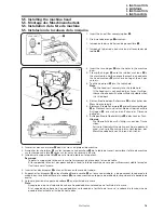
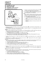
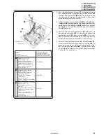
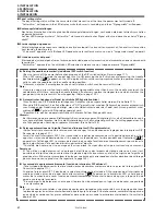
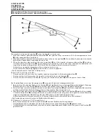
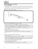
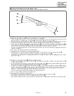
5. Pass the synchronizer harness
!0
, the operation panel
harness
!1
and the home position sensor harness
!2
through the cord clamp
q
, and then pull them into
the control box through the upper hole in the control
box and connect the connectors.
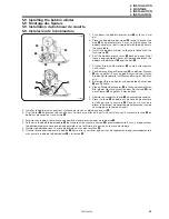
5. Führen Sie das Synchronisatorkabel
!0
, das Bedienung-
sfeldkabel
!1
und das Kabel des Ausgangspositionssen-
sors
!2
durch die Kabelklemme
q
, ziehen Sie sie durch
das obere Loch in den Schaltkasten ein und schließen
Sie die Stecker an.
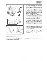
5. Passer le faisceau de synchroniseur
!0
, le faisceau de
panneau de commande
!
1
et le faisceau de capteur de
position d’origine
!2
par le serre-fils
q
, puis les tirer
dans le boîtier de commande par le trou supérieur du
boîtier de commande et brancher les connecteurs.
5. Pasar el mazo de conductores del sincronizador
!0
,
el mazo de conductores del panel de controles
!1
y el
mazo de conductores del sensor de posición inicial
!2
a través del sujetacables
q
, y luego tirar de ellos
en la caja de controles a través del agujero superior
y conectar los conectores.
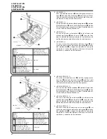
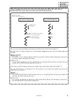
!2
P11
ORG
!0
Harness
Kabel
Faisceau
Mazo de conductores
P.C. board indication
Platinenmarkierung
Indication de la carte P.C.
Indicación de la tarjeta PC
Synchronizer <5-pin>
(Tube marked “3”)
Synchronisator <5polig>
(Rohr mit der Bezeichnung “3”)
Synchroniseur <5 broches>
(Tube portant la marque “3”)
Sincronizador <5 patillas>
(Caño marcado “3”)
P3 SYNCRO
Operation panel <20-pin>
(Black connector)
Bedienungsfeld <20polig>
(schwarzer Stecker)
Panneau de commande
<20 broches>
(Connecteur noir)
Panel de controles <20 patillas>
(Conector negro)
P4 PANEL
!1
Home position sensor <12-pin>
(Tube marked “11”)
Ausgangspositionssensor
<12polig>
(Rohr mit der Bezeichnung “11”)
Capteur de position d’origine
<12 broches>
(Tube portant la marque “11”)
Sensor de posición inicial
<12 patillas>
(Caño marcado “11”)
P11 ORG
q
P4 PANEL
P3 SYNCRO
!0
!1
!2
5. INSTALLATION
5. MONTAGE
5. INSTALLATION
5. INSTALACION
1293M

