


Configuration Mode (ConF)
94
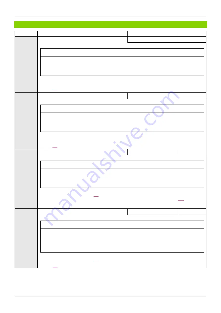
Code
Nam e / De s cription
Adjus tment range
Factory s e tting
SdC2
*
[Auto DC inj. level 2]
0 to 1.2 In (1)
0.5 In (1)
NOTICE
OVERHEATING AND DAMAGE TO THE MOTOR
Verify that the connected m otor is properly rated for the DC injection current to be applied in term s of am ount
and tim e in order to avoid overheating and dam age to the m otor.
Failure to follow these instructions can result in equipment damage.
2nd level of standstill DC injection current.
This parameter can be accessed if
[Auto DC inje ction]
(AdC)
is not
[No]
(nO)
.
See page
177
.
tdC2
*
[Auto DC inj. time 2]
0 to 30 s
0 s
NOTICE
OVERHEATING AND DAMAGE TO THE MOTOR
Verify that the connected m otor is properly rated for the DC injection current to be applied in term s of am ount
and tim e in order to avoid overheating and dam age to the m otor.
Failure to follow these instructions can result in equipment damage.
2nd standstill injection time.
This parameter can be accessed if
[Auto DC inje ction]
(AdC)
is set to
[Ye s ]
(YES)
.
See page
177
.
SFr
[Switching freq.]
2 to 16 kHz
4.0 kHz
NOTICE
DAMAGE TO THE MOTOR
Verify that the s witching frequency of the drive does not exceed 4 kHz if the EMC filter is dis connected for
operation of the drive in an IT m ains .
Failure to follow these instructions can result in equipment damage.
This applies to the follow ing drive versions: ER24-…K/B
Sw itching frequency setting. See page
119
.
Adjus tment range:
The maximum value is limited to 4 kHz if
[M otor s urge lim it]
(SUL)
parameter, page
120
is configured.
Note :
In the event of excessive temperature rise, the drive w ill automatically reduce the sw itching frequency and reset it once
the temperature returns to normal.
CLI
*
[Current Limitation]
0 to 1.5 In (1)
1.5 In (1)
NOTICE
OVERHEATING AND DAMAGE TO THE MOTOR
•
Verify that the m otor is properly rated for the m axim um current to be applied to the m otor.
•
Cons ider the duty cycle of the m otor and all factors of your application including derating requirements in
determ ining the current lim it.
Failure to follow these instructions can result in equipment damage.
Used to limit the motor current. See page
218
.
Note :
If the setting is less than 0.25 In, the drive may lock in
[Output Phas e Loss]
(OPL)
fault mode if this has been enabled
(see page
256
). If it is less than the no-load motor current, the motor cannot run.
Parameters described in this page can be accessed by:
DRI- > CONF > FULL > SET-
Summary of Contents for ER24 Series
Page 6: ...6 Table of Contents ...
Page 14: ...16 ...
Page 34: ...Overview 36 ...
Page 40: ...42 ...
Page 74: ...Monitoring Mode MOn 76 ...
Page 241: ......
Page 278: ...Configuration Mode ConF 278 Access Level See Access Level LAC page 280 ...
Page 294: ...Interface ItF 294 ...
Page 298: ...298 Open Save as trA ...
Page 302: ...Multipoint Screen 302 ...
Page 304: ...304 ...
Page 306: ...Maintenance 306 ...
Page 316: ...Diagnostics and Troubleshooting 316 ...
Page 318: ...318 ...
Page 340: ...Index of Parameter Codes 340 ...
Page 343: ......
Page 344: ...Index of Parameter Codes 342 ER24_Programming_Manual_EN_01 2017 ...


