


Configuration Mode (ConF)
207
Scaling of feedback and references:
•
[Min PID feedback]
(PIF1)
,
[Max PID feedback]
(PIF2)
param eters can be us ed to s cale the PID
feedback (s ens or range).
This scale MUST be maintained for all other parameters.
•
[Min PID reference]
(PIP1)
,
[Max PID reference]
(PIP2)
param eters can be us ed to s cale the
adjus tm ent range, for exam ple the reference.
The adjustment range MUST remain within the sensor
range.
The m axim um value of the scaling parameters is 32,767. To facilitate installation, we recommend using values
as clos e as pos sible to this m axim um level, while retaining powers of 10 in relation to the actual values .
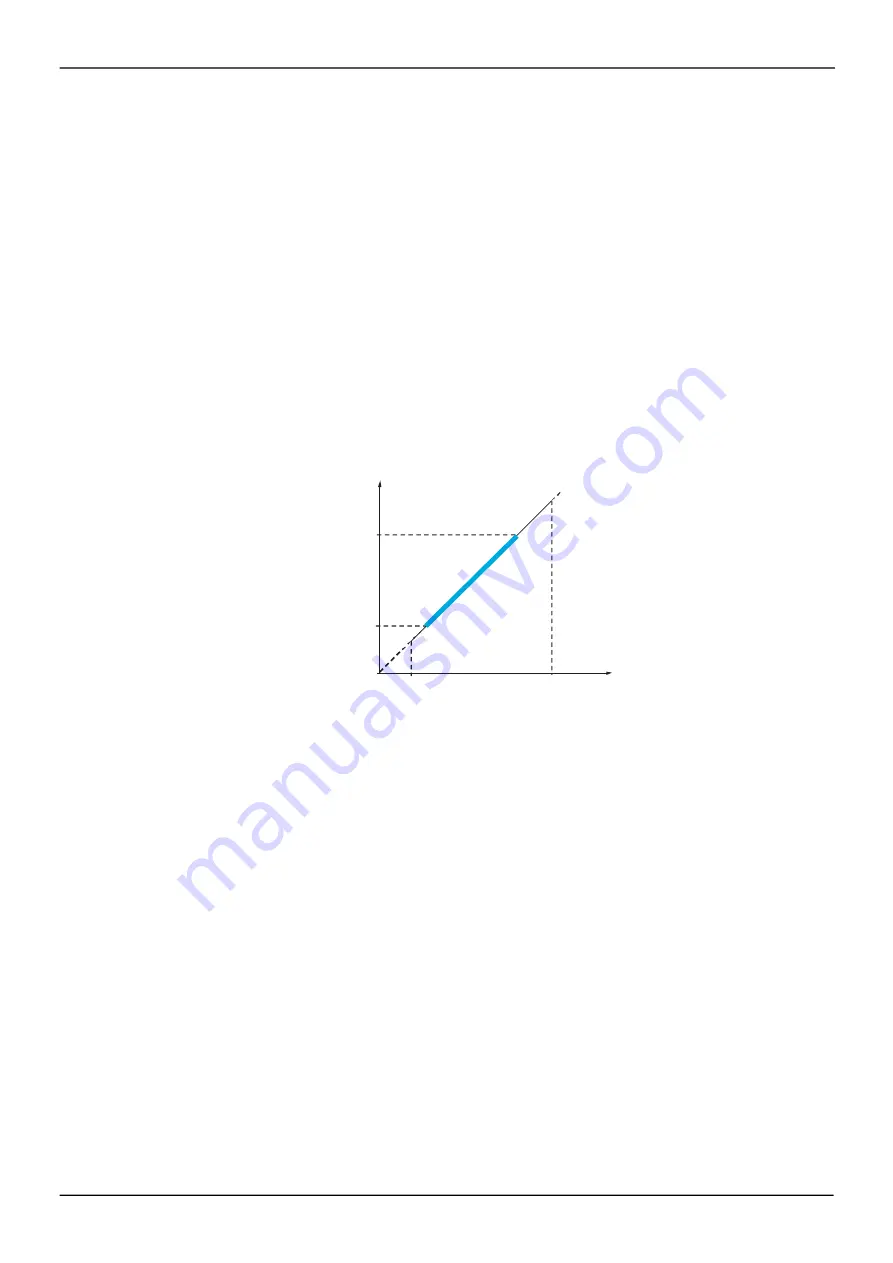
Example
(s ee graph below): Adjus tm ent of the volum e in a tank, between 6 m
3
and 15 m
3
.
•
Sens or us ed 4-20 m A, 4.5 m
3
for 4 m A and 20 m
3
for 20 m A, with the res ult that
PIF1
= 4,500 and
PIF2
= 20,000.
•
Adjus tm ent range 6 to 15 m
3
, with the res ult that
PIP1
= 6,000 (m in. reference) and
PIP2
= 15,000
(m ax. reference).
•
Exam ple references :
- rP1 (internal reference) = 9,500
- rP2 (pres et reference) = 6,500
- rP3 (pres et reference) = 8,000
- rP4 (pres et reference) = 11,200
The
[3.4 DISPLAY CONFIG.]
m enu can be us ed to cus tom ize the nam e of the unit dis played and its form at.
Adjustment range
(reference)
PIP2 (15,000)
PIP1 (6,000)
PIF1
(4,500)
PIF2
(20,000)
PID feedback
Other parameters:
•
[PID wake up thresh.]
(rSL)
param eter: Can be us ed to s et the PID error thres hold, above which the
PID regulator will be reactivated (wake-up) after a s top due to the m ax. tim e thres hold being exceeded at
low s peed
[Low speed time out]
(tLS)
.
•
Revers al of the direction of correction
[PID correct. reverse]
(PIC)
: If
[PID correct. reverse]
(PIC)
is
s et to
[No]
(nO)
, the s peed of the m otor will increas e when the error is pos itive (for exam ple: pres s ure
control with a com pres sor). If
[PID correct. reverse]
(PIC)
is s et to
[Yes]
(YES)
, the s peed of the m otor
will decreas e when the error is pos itive (for exam ple: tem perature control us ing a cooling fan).
•
The integral gain m ay be s hort-circuited by a logic input.
•
An alarm on the PID feedback m ay be configured and indicated by a logic output.
•
An alarm on the PID error m ay be configured and indicated by a logic output.
Summary of Contents for ER24 Series
Page 6: ...6 Table of Contents ...
Page 14: ...16 ...
Page 34: ...Overview 36 ...
Page 40: ...42 ...
Page 74: ...Monitoring Mode MOn 76 ...
Page 241: ......
Page 278: ...Configuration Mode ConF 278 Access Level See Access Level LAC page 280 ...
Page 294: ...Interface ItF 294 ...
Page 298: ...298 Open Save as trA ...
Page 302: ...Multipoint Screen 302 ...
Page 304: ...304 ...
Page 306: ...Maintenance 306 ...
Page 316: ...Diagnostics and Troubleshooting 316 ...
Page 318: ...318 ...
Page 340: ...Index of Parameter Codes 340 ...
Page 343: ......
Page 344: ...Index of Parameter Codes 342 ER24_Programming_Manual_EN_01 2017 ...


