


RTD Module Installation
3.13
RTD Module Installation
3.13.1
Location
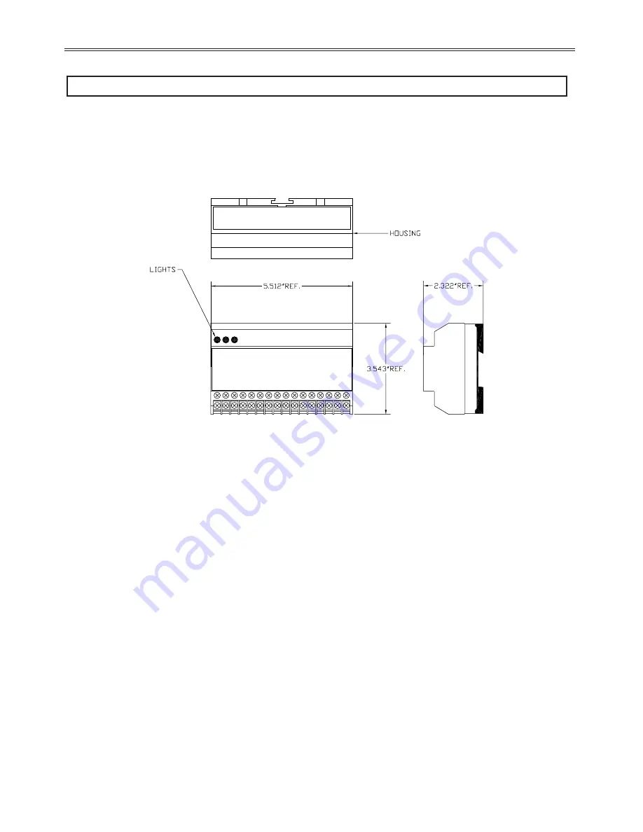
The mounting location for the Remote RTD Module should be chosen to give easy access to the RTD wiring, control terminals and
indicator LEDs as well as providing a location to mount the power supply. The Remote RTD Module is specifically designed to be
mounted close to the equipment it is monitoring. This eliminates long RTD wire lengths which save time and money on installation and
wiring. The Benshaw Remote RTD Module is designed to mount on industry standard 35mm wide by 7.5mm deep DIN rail.
3.13.2
Modbus Address
Set the rotary switch on the top of the Remote RTD Module to the desired Modbus address. Up to 2 modules can be connected to the
EXMVRMX
3
starter. The address set by the rotary switch must match the setting in RTD 01 or RTD 02. For example, setting both the
rotary switch and RTD 01 to 16 would make the connected module be module #1. The connected RTDs would then represent #1 to #8 in
the RTD programming.
3.13.3
Power Connections
The 24VDC power source is connected to the following terminals.
•
24VDC-: Negative connection to 24VDC power supply
•
24VDC+: Positive connection to 24VDC power supply
•
"
g
": Chassis ground connection
3.13.4
RS-485 Communication
The RS-485 communications wiring should use shielded twisted pair cable. The shield should only be terminated at one end. The
connections are as follows:
MX RJ45
Module
Description
pin 5
A(-)
RS-485 negative communications connection
pin 4
B(+)
RS-485 positive communications connection
pin 8
Com
RS-485 common connection
36
3 - INSTALLATION
Figure 22: Remote RTD Module Mechanical Layout
Summary of Contents for RediStart EXEXMVRMX3 Series
Page 2: ......
Page 10: ......
Page 11: ...1 Introduction 1...
Page 17: ...2 Technical Specifications 7...
Page 27: ...3 Installation 17...
Page 48: ......
Page 49: ...4 Keypad Operation 39...
Page 59: ...5 Parameter Groups 49...
Page 67: ...6 Parameter Description 57...
Page 122: ...NOTES 112 6 PARAMETER DESCRIPTION...
Page 123: ...7 Theory of Operation 113...
Page 155: ...NOTES 145 7 THEORY OF OPERATION...
Page 156: ...146 7 THEORY OF OPERATION...
Page 157: ...8 Troubleshooting Maintenance 147...
Page 185: ...NOTES 175 8 TROUBLESHOOTING MAINTENANCE...
Page 186: ......
Page 187: ...Appendices 177...
Page 213: ...203 APPENDIX H 3 YEAR WARRANTY...
Page 221: ...Publication History Revision Date ECO 00 12 15 06 Initial Release...


