


As described in Section 1,
General Information, Differential Protection Application Considerations
, when
the zone of protection includes a transformer, it may be necessary to provide phase angle and zero
sequence compensation to the currents used by the differential protection elements (see Figure 3-5). For
each input circuit, a setting is provided to enter the transformer connections associated with that input. If
there is no transformer within the protected zone, this setting should be set to
NA (not applicable)
.
Determining the Transformer Connection Parameters
Wye and Autotransformer Windings.
The transformer connection for a CT input circuit that is
connected to either a wye or autotransformer winding should be classified as a wye winding.
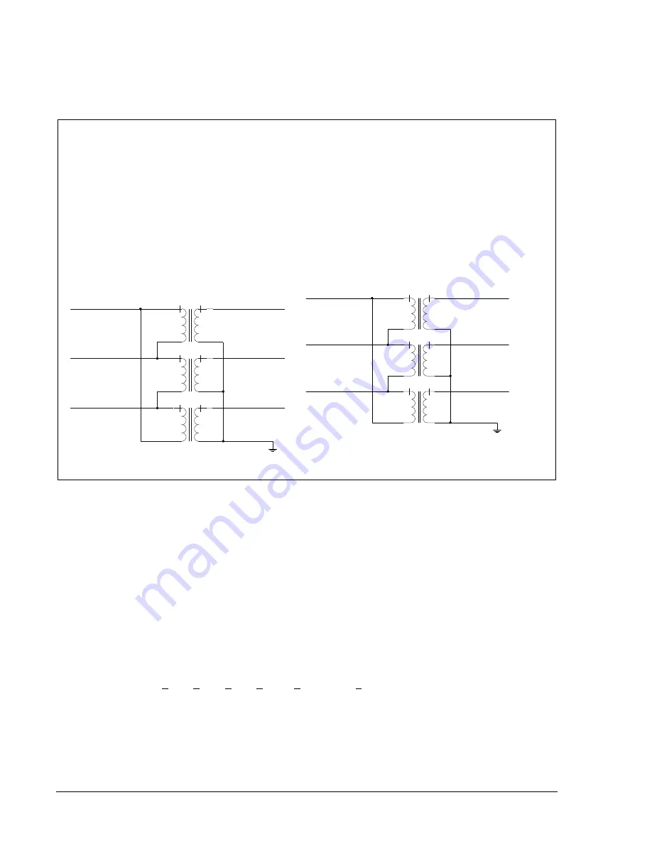
Delta Transformer Windings.
The transformer connection for a CT input circuit that is connected to a
delta winding could be classified as one of two delta connections: Delta IA-IB (DAB) or Delta IA-IC
(DAC). A delta configuration is defined by the currents that flow in the primary phases connected to the
delta. The wye winding phase connections are used as the point of reference since the current that
flows in the wye winding is the same as the current in the wye side primary phases. Figure 3-5a shows
an example of a transformer with a DAB connection. Figure 3-5b shows an example of the same
transformer with the phases reconnected to provide a DAC connection. If there is no wye winding to
use as reference, as is the case with a delta/delta transformer, the definition of the delta configuration
is not important.
B
A
C
b
a
c
D2837-21
02-17-04
IC=Ic-Ia
IB=Ib-Ic
IA=Ia-Ib
B
C
A
b
c
a
D2837-22
03-25-03
IA=Ia-Ic
IB=Ib-Ia
IC=Ic-Ib
Figure 3-5a. DAB Delta
Figure 3-5b. DAC Delta
Figure 3-5. DAB/DAC Delta
With the appropriate CT and transformer connection information, the relay can automatically determine
the correct compensation required. Normally, all circuits are compensated to obtain their equivalent delta
currents. If all transformer windings and CTs are connected in wye, a special case exists and no
compensation is required. For this case, wye currents can be used directly.
Total compensation is accomplished by summing the appropriate phasors from each of the CT inputs
prior to using them in the differential function. For a WYE to DAB connection, the WYE CT phasors must
first be phase-compensated to match the DAB circuit’s 30° shift. This is done using the DAB
compensator, which provides a phasor sum of Ia + Ib to form I’a for comparison to the DAB’s Ia CT
current. A similar operation is used to form I’b and I’c.
Total compensation uses six phase compensation factors: DAB, DAC, REV, Rotation Factors R1 and R2,
WYE, and Double Delta DDAB. The compensation factors are used in various combinations to
compensate for the +30°, +60°, +90°, +120°, +150°, and +180° phase shifts that are possible in
transformers and sensing CT configurations.
Mathematically, the compensation factors provide the following:
Note: A 1/(square root of 3) factor is missing from the compensation equations. See Table 3-6 for the net
compensation equations.
3-8
BE1-CDS240 Input and Output Functions
9365200990 Rev F
Summary of Contents for BE1-CDS240
Page 2: ......
Page 8: ...vi BE1 CDS240 Introduction 9365200990 Rev F This page intentionally left blank ...
Page 38: ...1 28 BE1 CDS240 General Information 9365200990 Rev F This page intentionally left blank ...
Page 40: ...ii BE1 CDS240 Quick Start 9365200990 Rev F This page intentionally left blank ...
Page 152: ...ii BE1 CDS240 Metering 9365200990 Rev F This page intentionally left blank ...
Page 226: ...iv BE1 CDS240 Application 9365200990 Rev F This page intentionally left blank ...
Page 286: ...ii BE1 CDS240 Security 9365200990 Rev F This page intentionally left blank ...
Page 290: ...9 4 BE1 CDS240 Security 9365200990 Rev F This page intentionally left blank ...
Page 292: ...ii BE1 CDS240 Human Machine Interface 9365200990 Rev F This page intentionally left blank ...
Page 306: ...10 14 BE1 CDS240 Human Machine Interface 9365200990 Rev F This page intentionally left blank ...
Page 308: ...ii BE1 CDS240 ASCII Command Interface 9365200990 Rev F This page intentionally left blank ...
Page 342: ...11 34 BE1 CDS240 ASCII Command Interface 9365200990 Rev F This page intentionally left blank ...
Page 349: ...Figure 12 5 Horizontal Rack Mount Front View 9365200990 Rev F BE1 CDS240 Installation 12 5 ...
Page 361: ...Figure 12 17 Typical DC Connection Diagrams 9365200990 Rev F BE1 CDS240 Installation 12 17 ...
Page 372: ...12 28 BE1 CDS240 Installation 9365200990 Rev F This page intentionally left blank ...
Page 468: ...13 92 BE1 CDS240 Testing and Maintenance 9365200990 Rev F This page intentionally left blank ...
Page 512: ...14 42 BE1 CDS240 BESTCOMS Software 9365200990 Rev F This page intentionally left blank ...
Page 544: ...ii BE1 CDS240 Terminal Communication 9365200990 Rev F This page intentionally left blank ...
Page 550: ...ii BE1 CDS240 Settings Calculations 9365200990 Rev F This page intentionally left blank ...
Page 578: ...D 28 BE1 CDS240 Settings Calculations 9365200990 Rev F This page intentionally left blank ...
Page 579: ......


