


9365200990 Rev F
BE1-CDS240 Testing and Maintenance
13-5
Power Up
Purpose
: To verify that the relay performs the power-up sequence.
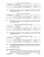
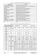
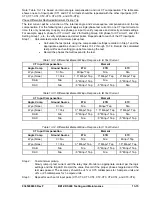
Step 1: Apply voltage to input power terminals B2 and B3. Table 13-1 shows the appropriate voltage
for each relay style.
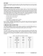
Table 13-1. Voltage Input
Style Number
Voltage Input
BE1-CDS2 4 0 - x x 3 N
1
x x N x x x 48/125 Vac/dc
BE1-CDS2 4 0 - x x 3 N
2
x x N x x x
125/250 Vac/dc
BE1-CDS2 4 0 - x x 3 N
3
x x N x x x 24
Vdc
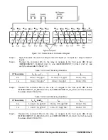
Step 2: Verify that the
Power
LED is on and that characters are displayed on the HMI display. Upon
power-up, the relay will perform a brief self-test.
During this brief test, all front panel LEDs will flash momentarily, the display will indicate each
step of the self test, relay model, software version and then settle into the default display
screen. Contact Basler Electric, Customer Service if anything appears out of the ordinary or if
LCD code error messages appear.
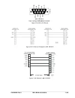
Communications
Purpose:
To verify that the BE1-CDS240 relay communicates through all ports:
Reference Commands:
ACCESS, EXIT
To communicate with the BE1-CDS240 through any of the three ports, you may use either a VT-100
terminal or a personal computer (PC) with a serial port and suitable communications software. There is a
VT100 terminal emulation program embedded in BESTCOMS, under the
Communication
pull-down
menu. The relay communication default settings for terminal emulation are:
Baud Rate = 9,600 bps
Data Bits = 8
Stop Bit =1
Parity = none
Flow Control = Xon/Xoff.
See Appendix C for more information on Terminal and HyperTerminal setups for Windows
operating
systems.
Note: The preferred method to communicate is by using “Basler Terminal” which can be accessed
through BESTCOMS by clicking on the Communications tab and then Terminal (VT100 Emulation).
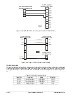
Set Up the Relay to Communicate with the PC
Step 1: Depress the
UP
arrow pushbutton twice to get to the top level of the menu tree. Depress the
LEFT
or
RIGHT
arrow pushbuttons until the \SETUP\GENERAL SETTINGS Screen appears.
Next, depress the
DOWN
arrow pushbutton two times to get to the sublevel menu \SETUP
\COM \COM0 Screen. With the
RIGHT
arrow pushbutton, scroll one screen to the right. These
are the settings for the relay rear RS-232 (COM 1) port. Verify that the baud rate is 9,600 bps.
Step 2:
Connect the serial cable between the terminal or PC and the rear RS-232 port (COM 1) on the
relay.
Step 3:
Initiate the communication program for your computer/terminal.
Step 4:
Transmit the command
ACCESS=
(You may use the shortcut keystrokes and just enter a=.)
RESULT: The relay should respond with
ACCESS GRANTED: GLOBAL
.
Step 5:
Transmit
EXIT
.
Step 6:
Repeat Steps 1, 2 and 3 for the front RS-232 port (COM 0).
Step 7:
Connect the male end of the terminal cable to the RS-232 Port on a RS-232/485 converter
box. Connect the RS-485 output of the converter box to the relay RS-485 terminals (COM 2)
and repeat Steps 1, 2 and 3.
Summary of Contents for BE1-CDS240
Page 2: ......
Page 8: ...vi BE1 CDS240 Introduction 9365200990 Rev F This page intentionally left blank ...
Page 38: ...1 28 BE1 CDS240 General Information 9365200990 Rev F This page intentionally left blank ...
Page 40: ...ii BE1 CDS240 Quick Start 9365200990 Rev F This page intentionally left blank ...
Page 152: ...ii BE1 CDS240 Metering 9365200990 Rev F This page intentionally left blank ...
Page 226: ...iv BE1 CDS240 Application 9365200990 Rev F This page intentionally left blank ...
Page 286: ...ii BE1 CDS240 Security 9365200990 Rev F This page intentionally left blank ...
Page 290: ...9 4 BE1 CDS240 Security 9365200990 Rev F This page intentionally left blank ...
Page 292: ...ii BE1 CDS240 Human Machine Interface 9365200990 Rev F This page intentionally left blank ...
Page 306: ...10 14 BE1 CDS240 Human Machine Interface 9365200990 Rev F This page intentionally left blank ...
Page 308: ...ii BE1 CDS240 ASCII Command Interface 9365200990 Rev F This page intentionally left blank ...
Page 342: ...11 34 BE1 CDS240 ASCII Command Interface 9365200990 Rev F This page intentionally left blank ...
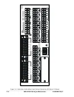
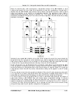
Page 349: ...Figure 12 5 Horizontal Rack Mount Front View 9365200990 Rev F BE1 CDS240 Installation 12 5 ...
Page 361: ...Figure 12 17 Typical DC Connection Diagrams 9365200990 Rev F BE1 CDS240 Installation 12 17 ...
Page 372: ...12 28 BE1 CDS240 Installation 9365200990 Rev F This page intentionally left blank ...
Page 468: ...13 92 BE1 CDS240 Testing and Maintenance 9365200990 Rev F This page intentionally left blank ...
Page 512: ...14 42 BE1 CDS240 BESTCOMS Software 9365200990 Rev F This page intentionally left blank ...
Page 544: ...ii BE1 CDS240 Terminal Communication 9365200990 Rev F This page intentionally left blank ...
Page 550: ...ii BE1 CDS240 Settings Calculations 9365200990 Rev F This page intentionally left blank ...
Page 578: ...D 28 BE1 CDS240 Settings Calculations 9365200990 Rev F This page intentionally left blank ...
Page 579: ......


