


9365200990 Rev F
BE1-CDS240 Testing and Maintenance
13-25
Purpose:
To set the transformer counter and duty registers as required for the system
installation.
Reference Commands:
RT-TFCNTR, RT-DUTY
Refer to Section 6,
Reporting and Alarm Functions, Transformer Monitoring,
for setting details. To use the
front panel HMI, go to Screen 4.5.1.
Breaker Monitoring
If the relay Breaker Monitoring feature is enabled, reset the counter and duty registers to zero or an
existing value.
Purpose:
To set the breaker counter and duty registers as required for the system installation.
Reference Commands:
RB-OPCNTR, RB-DUTY
Refer to Section 6,
Reporting and Alarm Functions, Breaker Monitoring,
for setting details. To use the
front panel HMI, go to Screen 4.3.1.
Relay Trouble Alarms
Reset and verify that the relay trouble alarm is not ON. Alarm information can be read by transmitting the
ASCII commands RA or RG-STAT. To clear (reset) a relay trouble alarm, first gain write access to the
reporting functions (R password) and then initiate the RA=0 or RA-REL=0 commands or press the
Reset
key while the front panel HMI Screen 1.2, \STAT\ALARMS\ALARM is displayed.
Purpose:
To verify that all alarms are cleared and no alarms are active before initially loading the system.
Reference Commands:
RA, RG-STAT, RA=0, RA-REL=0
Refer to Section 6,
Reporting and Alarm Functions, Major/Minor/Logic Programmable Alarms,
for
information on setting alarms and retrieving and resetting alarm reports. To use the front panel HMI, go to
Screen 1.2, \STAT\ALARMS\ALARM.
Major/Minor/Logic Programmable Alarms
Reset and verify that the relay Major/Minor/Logic Programmable
alarms are not ON. Alarm information
can be read by transmitting the ASCII commands RA or RG-STAT. To clear (reset) a relay
Major/Minor/Logic alarm, first gain write access to the reporting functions (R password) and then initiate
the RA=0 or RA-MAJ/MIN/LGC=0 commands or press the
Reset
key while the front panel HMI Screen
1.2.1, \STAT\ALARMS\DETAILS is displayed.
Purpose:
To verify that all Major/Minor/Logic Programmable
alarms are cleared and no alarms are active
before initially loading the system.
Reference Commands:
RA, RG-STAT, RA=0, RA-MAJ/MIN/LGC =0
Refer to Section 6,
Reporting and Alarm Functions, Major/Minor/Logic Programmable Alarms,
for
information on setting alarms and retrieving and resetting alarm reports. To use the front panel HMI, go to
Screen 1.2.1, \STAT\ALARMS\DETAILS.
Targets
Reset and verify that there is no target information. Target information can be read by transmitting the
ASCII command RG-TARG. To clear (reset) a relay target, first gain write access to the reporting
functions (R password) and then initiate the RG-TARG=0 command or press the
Reset
key while the front
panel HMI Screen 1.1, \STAT\TARGETS is displayed.
Purpose:
To verify that all targets are cleared before initially loading the system.
Reference Commands:
RG-TARG, RG-TARG=0
Refer to Section 6,
Reporting and Alarm Functions, Fault Reporting, Targets,
for information on setting
targets and retrieving and resetting target information. To use the front panel HMI, go to Screen 1.1,
\STAT\TARGETS.
Fault Summary Reports
Reset and verify that new fault summary directory records are set to zero. To reset the new fault summary
directory records, first gain write access to the reporting functions (R password) and then initiate the RF-
NEW=0 command two times. Verify that there are no new fault summary records by initiating the RF
command and observe that the NEW FAULTS line indicates zero or view the front panel HMI Screen 4.1,
\REPRT\FAULT.
Purpose:
To verify that there is no new fault records before initially loading the system.
Reference Commands:
RF, RF-NEW=0
Summary of Contents for BE1-CDS240
Page 2: ......
Page 8: ...vi BE1 CDS240 Introduction 9365200990 Rev F This page intentionally left blank ...
Page 38: ...1 28 BE1 CDS240 General Information 9365200990 Rev F This page intentionally left blank ...
Page 40: ...ii BE1 CDS240 Quick Start 9365200990 Rev F This page intentionally left blank ...
Page 152: ...ii BE1 CDS240 Metering 9365200990 Rev F This page intentionally left blank ...
Page 226: ...iv BE1 CDS240 Application 9365200990 Rev F This page intentionally left blank ...
Page 286: ...ii BE1 CDS240 Security 9365200990 Rev F This page intentionally left blank ...
Page 290: ...9 4 BE1 CDS240 Security 9365200990 Rev F This page intentionally left blank ...
Page 292: ...ii BE1 CDS240 Human Machine Interface 9365200990 Rev F This page intentionally left blank ...
Page 306: ...10 14 BE1 CDS240 Human Machine Interface 9365200990 Rev F This page intentionally left blank ...
Page 308: ...ii BE1 CDS240 ASCII Command Interface 9365200990 Rev F This page intentionally left blank ...
Page 342: ...11 34 BE1 CDS240 ASCII Command Interface 9365200990 Rev F This page intentionally left blank ...
Page 349: ...Figure 12 5 Horizontal Rack Mount Front View 9365200990 Rev F BE1 CDS240 Installation 12 5 ...
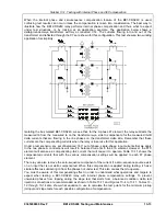
Page 361: ...Figure 12 17 Typical DC Connection Diagrams 9365200990 Rev F BE1 CDS240 Installation 12 17 ...
Page 372: ...12 28 BE1 CDS240 Installation 9365200990 Rev F This page intentionally left blank ...
Page 468: ...13 92 BE1 CDS240 Testing and Maintenance 9365200990 Rev F This page intentionally left blank ...
Page 512: ...14 42 BE1 CDS240 BESTCOMS Software 9365200990 Rev F This page intentionally left blank ...
Page 544: ...ii BE1 CDS240 Terminal Communication 9365200990 Rev F This page intentionally left blank ...
Page 550: ...ii BE1 CDS240 Settings Calculations 9365200990 Rev F This page intentionally left blank ...
Page 578: ...D 28 BE1 CDS240 Settings Calculations 9365200990 Rev F This page intentionally left blank ...
Page 579: ......


