


Function Block Logic Settings
Each function block is equivalent to its discrete device counterpart. For example, the phase percentage
differential function block in the BE1-CDS240 relay shown in Figure 7-1 has many of the characteristics of
a BE1-87T transformer differential relay.
Before using a protection or control function block, two items must be set: the
Mode
and the
Input Logic
.
Setting the
Mode
is equivalent to deciding which protection or control functions will be used in a logic
scheme. The
Input Logic
establishes control of a function block.
Mode and input logic information is contained in logic setting command strings. Depending on the
command, the mode setting can either enable or disable a logic input or determine how a function block
operates. Input logic defines which logic variables control or disable a logic function. An example of an
input logic equation is SL-87=1,IN2. In this differential logic command string, the 1 parameter indicates
that the 87 function is enabled. The IN2 expression indicates that the 87 function will be blocked when
input two goes TRUE.
The AND operator may not be applied to the terms of an input logic equation. Any number of variables or
their inverse can be combined in a function element input logic expression. Section 4,
Protection and
Control,
provides detailed information about setting the logic for each function element.
Output Logic Settings
Defining Output Operation
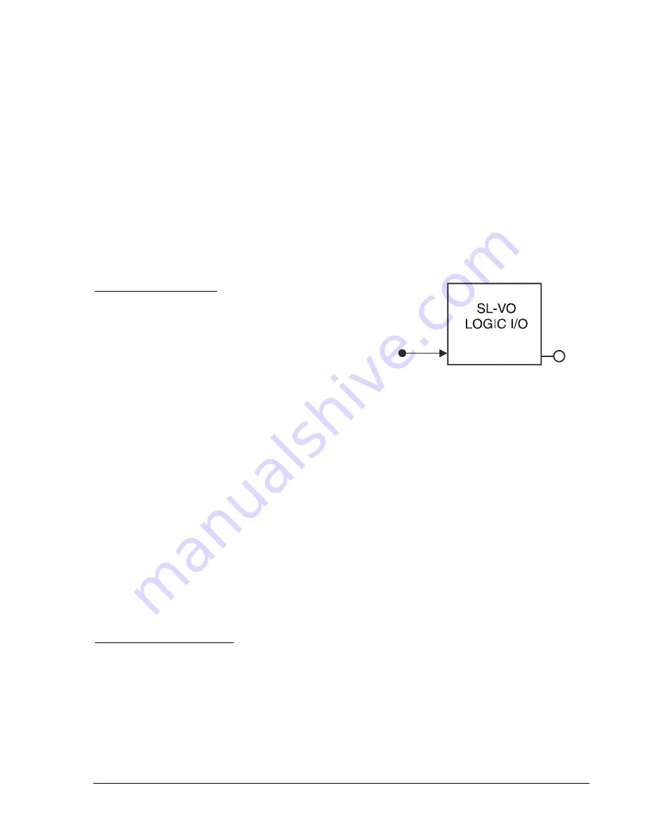
VO[n]
LOGIC
EQUATION
D2861-16
08-21-03
Output operation is defined by Boolean logic equations. Each
variable in an equation corresponds to the current state
(evaluated every quarter cycle) of an input, output, or timer.
Figure 7-6 illustrates this relationship. Every quarter cycle,
output expressions are evaluated as TRUE or FALSE. If a
logic output that corresponds to a hardware output changes
state, then the corresponding output relay contact also
changes state.
Figure 7-6. Virtual Output Logic
When the relay is powered up, all logic outputs are disabled and most variables (including virtual outputs)
initialize as FALSE. Some variable states are stored in EEPROM and are restored to the last state prior to
loss of power. These variables include 43/143/243/343/443/543/643/743,101SC, 1101SC, 2101SC,
3101SC, and SG0 through SG3. All control commands, including logic override control, are also stored in
EEPROM. If you override output logic and force an output to open, that condition will be maintained even
if operating power is cycled.
When the logic is running and logic expression SL-VO[n] is FALSE, then output VO[n] = 0. When the logic
is running and logic expression SL-VO[n] is TRUE, then VO[n] = 1. Hardware Output OUTA follows the
corresponding Logic Output VOA. Hardware outputs 1 through 14 can be operated by any virtual output
(SL-VO(n)) or combination.
Logic equations are defined by logic variables, logic operators, and their position in an equation. The
available logic operators include AND (
), OR (+) and NOT (/). The NOT operator is applied to the
variable immediately following the symbol (/). For virtual output equations, OR logic can be applied to any
number of variables if no AND logic is used in the expression. Similarly, AND logic can be applied to any
number of variables if no OR logic is used. Any number of NOT operators may be used. For complex
expressions that use both AND and OR operators, OR logic is limited to four terms. Up to four AND terms
with any number of variables can be ORed together. When the relay is processing a complex expression,
it performs AND operations before performing OR operations.
Virtual and Hardware Outputs
A virtual output exists only as a logical state inside the relay (VO1 through VO15). A hardware output is a
physical relay contact that can be used for protection or control. The BE1-CDS240 relay has up to 14
isolated output contacts (I/O Option E) (OUT1 - OUT14) consisting of two Form C output contacts
(OUT1,2) and 12 Form A output contacts (OUT 3-14). I/O Option A consists of 10 outputs. Alarm contact
output, OUTA, is a Form B contact so that upon loss of power, it will "fail safe" close. Output contacts
OUT1 through OUT14 are controlled by the status of the internal virtual logic signals VO1 through VO15.
If VO[n] becomes TRUE, it can be mapped to any of the 14 output relays, operating the associated
contact. For the alarm output, if VOA becomes TRUE, the ALM output de-energizes and opens. For more
information about input and output functions, see Section 3,
Input and Output Functions.
9365200990 Rev F
BE1-CDS240 BESTlogic Programmable Logic
7-9
Summary of Contents for BE1-CDS240
Page 2: ......
Page 8: ...vi BE1 CDS240 Introduction 9365200990 Rev F This page intentionally left blank ...
Page 38: ...1 28 BE1 CDS240 General Information 9365200990 Rev F This page intentionally left blank ...
Page 40: ...ii BE1 CDS240 Quick Start 9365200990 Rev F This page intentionally left blank ...
Page 152: ...ii BE1 CDS240 Metering 9365200990 Rev F This page intentionally left blank ...
Page 226: ...iv BE1 CDS240 Application 9365200990 Rev F This page intentionally left blank ...
Page 286: ...ii BE1 CDS240 Security 9365200990 Rev F This page intentionally left blank ...
Page 290: ...9 4 BE1 CDS240 Security 9365200990 Rev F This page intentionally left blank ...
Page 292: ...ii BE1 CDS240 Human Machine Interface 9365200990 Rev F This page intentionally left blank ...
Page 306: ...10 14 BE1 CDS240 Human Machine Interface 9365200990 Rev F This page intentionally left blank ...
Page 308: ...ii BE1 CDS240 ASCII Command Interface 9365200990 Rev F This page intentionally left blank ...
Page 342: ...11 34 BE1 CDS240 ASCII Command Interface 9365200990 Rev F This page intentionally left blank ...
Page 349: ...Figure 12 5 Horizontal Rack Mount Front View 9365200990 Rev F BE1 CDS240 Installation 12 5 ...
Page 361: ...Figure 12 17 Typical DC Connection Diagrams 9365200990 Rev F BE1 CDS240 Installation 12 17 ...
Page 372: ...12 28 BE1 CDS240 Installation 9365200990 Rev F This page intentionally left blank ...
Page 468: ...13 92 BE1 CDS240 Testing and Maintenance 9365200990 Rev F This page intentionally left blank ...
Page 512: ...14 42 BE1 CDS240 BESTCOMS Software 9365200990 Rev F This page intentionally left blank ...
Page 544: ...ii BE1 CDS240 Terminal Communication 9365200990 Rev F This page intentionally left blank ...
Page 550: ...ii BE1 CDS240 Settings Calculations 9365200990 Rev F This page intentionally left blank ...
Page 578: ...D 28 BE1 CDS240 Settings Calculations 9365200990 Rev F This page intentionally left blank ...
Page 579: ......


