


Integration of Protection, Control, and I/O Elements
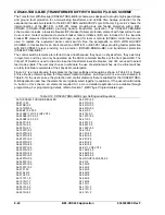
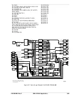
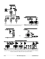
The logic settings in Table 8-13 also include the logic equations that establish the control connections
between elements of the CDS240-TXCL-B-BE scheme. For example, the three underlined commands in
the logic equations of Table 8-13 provide the electrical connection between the 87 element (trip enabled
by the settings) and trip outputs 1, 2, and 4. Referring to Figures 8-5 and 8-6, the 87 protection element
trips through Outputs 1, 2, and 4. The 151 and 51N protection elements (also trip enabled by the settings)
trip through Outputs 1 and 2 while the 251 protective element (also trip enabled by the settings) trips
through Output 4. Protection elements set at 0 are setting disabled and will not provide a trip output even
if logic enabled.
Virtual control switch elements enabled for use in this scheme are 101, 43, 143, 243, and 343. The 101
Control Switch trips the low-side breaker through Output 4 and closes the low-side breaker through
Output 5 if IN3 (86 input) is not TRUE. The high-side breaker is tripped by 43 through Output 2 and
closed by 143 through Output 3 if IN3 (86 input) is not TRUE. Control Switch 243 is used to turn the 87
function on or off.
Control of the active setting group can be manual or automatic. For the CDS240-TXCL-B-BE application,
setting group control is enabled for discrete input and automatic or manual control as determined by the
position of Virtual Switch 343.
Alarms
Three logic variables drive the front panel LEDs: Relay Trouble (ALMREL), Major Alarm (ALMMAJ), and
Minor Alarm (ALMMIN). A fourth logic variable, Logic Alarm (ALMLGC), has no associated front panel
LED. When the relay self-test detects a problem in the relay (ALMREL) as programmed for the CDS240-
TXCL-A-BE scheme, the Relay Trouble LED lights, Output A operates and all outputs are disabled. When
a Major Alarm is detected (ALMMAJ), the associated LED lights and Output 6 operates. When a Minor
Alarm (ALMMIN) is detected, the associated LED lights. But in this scheme, no output relay is
programmed to operate.
NOTE
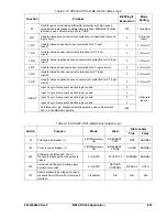
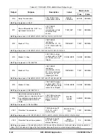
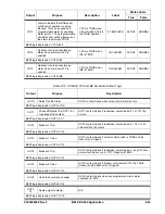
Tables 8-14 through 8-18 provide detailed logic definitions for the inputs, outputs,
protection, and control elements. Only those inputs, logic blocks, virtual switches,
and outputs in use for the CDS240-TXCL-B-BE preprogrammed logic are
described in the following tables.
Table 8-14. CDS240-TXCL-B-BE Contact Input Logic
State Labels
Input Purpose Name
Label
Energized De-Energized
IN1
Optional input. Used for CT input circuit 1 breaker
status indication in SER reports. TRUE when
breaker is closed.
BREAKER-1 CLOSED
OPEN
IN2
Optional input. Used for CT input circuit 2 breaker
status indication in SER reports. TRUE when
breaker is closed.
BREAKER-2 CLOSED
OPEN
IN3
Optional input. Used for 86 status indication and
locks out the low-side and high-side breakers
when TRUE. TRUE when 86 tripped.
86-TRIPPED TRIPPED
NORMAL
IN7, IN8
Optional inputs. Used for programmable alarms
and SER reporting. For example, sudden
pressure trip or transformer hot spot alarm, etc.
Drives VO14 and VO15 that are programmable
alarm points 22 and 23. Label inputs as
appropriate.
INPUT_7,
INPUT_8
CLOSED OPEN
8-20
BE1-CDS240 Application
9365200990 Rev F
Summary of Contents for BE1-CDS240
Page 2: ......
Page 8: ...vi BE1 CDS240 Introduction 9365200990 Rev F This page intentionally left blank ...
Page 38: ...1 28 BE1 CDS240 General Information 9365200990 Rev F This page intentionally left blank ...
Page 40: ...ii BE1 CDS240 Quick Start 9365200990 Rev F This page intentionally left blank ...
Page 152: ...ii BE1 CDS240 Metering 9365200990 Rev F This page intentionally left blank ...
Page 226: ...iv BE1 CDS240 Application 9365200990 Rev F This page intentionally left blank ...
Page 286: ...ii BE1 CDS240 Security 9365200990 Rev F This page intentionally left blank ...
Page 290: ...9 4 BE1 CDS240 Security 9365200990 Rev F This page intentionally left blank ...
Page 292: ...ii BE1 CDS240 Human Machine Interface 9365200990 Rev F This page intentionally left blank ...
Page 306: ...10 14 BE1 CDS240 Human Machine Interface 9365200990 Rev F This page intentionally left blank ...
Page 308: ...ii BE1 CDS240 ASCII Command Interface 9365200990 Rev F This page intentionally left blank ...
Page 342: ...11 34 BE1 CDS240 ASCII Command Interface 9365200990 Rev F This page intentionally left blank ...
Page 349: ...Figure 12 5 Horizontal Rack Mount Front View 9365200990 Rev F BE1 CDS240 Installation 12 5 ...
Page 361: ...Figure 12 17 Typical DC Connection Diagrams 9365200990 Rev F BE1 CDS240 Installation 12 17 ...
Page 372: ...12 28 BE1 CDS240 Installation 9365200990 Rev F This page intentionally left blank ...
Page 468: ...13 92 BE1 CDS240 Testing and Maintenance 9365200990 Rev F This page intentionally left blank ...
Page 512: ...14 42 BE1 CDS240 BESTCOMS Software 9365200990 Rev F This page intentionally left blank ...
Page 544: ...ii BE1 CDS240 Terminal Communication 9365200990 Rev F This page intentionally left blank ...
Page 550: ...ii BE1 CDS240 Settings Calculations 9365200990 Rev F This page intentionally left blank ...
Page 578: ...D 28 BE1 CDS240 Settings Calculations 9365200990 Rev F This page intentionally left blank ...
Page 579: ......


