


Mode 5, Integrating Timer
An integrating timer is similar to a pickup/dropout timer except that the PICKUP time T1 defines the rate
that the timer integrates toward timing out and setting the output to TRUE. Conversely, the RESET time
T2 defines the rate that the timer integrates toward dropout and resetting the output to FALSE. PICKUP
time T1 defines the time delay for the output to change to TRUE if the initiate input becomes TRUE and
stays TRUE. RESET time T2 defines the time delay for the output to change to FALSE if it is presently
TRUE and the initiate input becomes FALSE and stays FALSE.
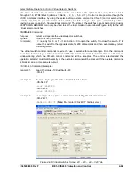
In the example shown in Figure 4-57, RESET time T2 is set to half of the PICKUP time T1 setting. The
initiate input expression becomes TRUE and the timer starts integrating toward pickup. Prior to timing out,
the initiate expression toggles to FALSE and the timer starts resetting at twice the rate as it was
integrating toward time out. It stays FALSE long enough for the integrating timer to reset completely but
then toggles back to TRUE and stays TRUE for the entire duration of time T1. At that point, the output of
the timer is toggled to TRUE. Then later, the initiate expression becomes FALSE and stays FALSE for the
duration of RESET time T2. At that point, the output of the timer is toggled to FALSE.
D2843-12
10-23-03
Figure 4-57. Mode 5, Integrating Timer
This type of timer is useful in applications where a monitored signal may be hovering at its threshold
between on and off. For example, it is desired to take some action when current is above a certain level
for a certain period. A 50T function could be used to monitor the current level. Thus, if the current level is
near the threshold so that the
INITIATE
input toggles between TRUE and FALSE from time to time, the
function will still time out as long as the time that it is TRUE is longer than the time that it is FALSE. With a
simple pickup/dropout timer, the timing function would reset to zero and start over each time the initiate
expression became FALSE.
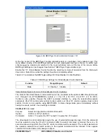
Mode 6, Latch
A one shot timer starts its timing sequence when the
INITIATE
input expression changes from FALSE to
TRUE. The timer will time for DELAY time T1 and then the output will latch TRUE. Additional
INITIATE
input expression changes of state are ignored. Time (T2) is ignored. Refer to Figure 4-58.
D2863-07
10-23-03
Figure 4-58. Mode 6, Latch
9365200990 Rev F
BE1-CDS240 Protection and Control
4-61
Summary of Contents for BE1-CDS240
Page 2: ......
Page 8: ...vi BE1 CDS240 Introduction 9365200990 Rev F This page intentionally left blank ...
Page 38: ...1 28 BE1 CDS240 General Information 9365200990 Rev F This page intentionally left blank ...
Page 40: ...ii BE1 CDS240 Quick Start 9365200990 Rev F This page intentionally left blank ...
Page 152: ...ii BE1 CDS240 Metering 9365200990 Rev F This page intentionally left blank ...
Page 226: ...iv BE1 CDS240 Application 9365200990 Rev F This page intentionally left blank ...
Page 286: ...ii BE1 CDS240 Security 9365200990 Rev F This page intentionally left blank ...
Page 290: ...9 4 BE1 CDS240 Security 9365200990 Rev F This page intentionally left blank ...
Page 292: ...ii BE1 CDS240 Human Machine Interface 9365200990 Rev F This page intentionally left blank ...
Page 306: ...10 14 BE1 CDS240 Human Machine Interface 9365200990 Rev F This page intentionally left blank ...
Page 308: ...ii BE1 CDS240 ASCII Command Interface 9365200990 Rev F This page intentionally left blank ...
Page 342: ...11 34 BE1 CDS240 ASCII Command Interface 9365200990 Rev F This page intentionally left blank ...
Page 349: ...Figure 12 5 Horizontal Rack Mount Front View 9365200990 Rev F BE1 CDS240 Installation 12 5 ...
Page 361: ...Figure 12 17 Typical DC Connection Diagrams 9365200990 Rev F BE1 CDS240 Installation 12 17 ...
Page 372: ...12 28 BE1 CDS240 Installation 9365200990 Rev F This page intentionally left blank ...
Page 468: ...13 92 BE1 CDS240 Testing and Maintenance 9365200990 Rev F This page intentionally left blank ...
Page 512: ...14 42 BE1 CDS240 BESTCOMS Software 9365200990 Rev F This page intentionally left blank ...
Page 544: ...ii BE1 CDS240 Terminal Communication 9365200990 Rev F This page intentionally left blank ...
Page 550: ...ii BE1 CDS240 Settings Calculations 9365200990 Rev F This page intentionally left blank ...
Page 578: ...D 28 BE1 CDS240 Settings Calculations 9365200990 Rev F This page intentionally left blank ...
Page 579: ......


