


element, start is successful. If 150TP times out first, the motor is tripped through Output 1. As described
under high inertia start, a motor could successfully start but still have abnormally high run currents. If
250TP, start/run current detection times out, 150TP (low inertia locked rotor protection) is defeated and
the same motor overload protection discussed above takes over.
Emergency Trip
An external emergency trip sensed at IN3 will initiate a trip of the breaker through Output 1 and seals the
trip path through V09. Virtual Output 13 goes high which drives alarm bit #21 in the programmable alarm
mask. The breaker cannot be closed until the seal-in is cleared by the Alarm Reset Key (ARSTKEY).
Alarms
Three logic variables drive the front panel LEDs: Relay Trouble (ALMREL), Major Alarm (ALMMAJ), and
Minor Alarm (ALMMIN). There is a fourth logic variable, Logic Alarm (ALMLGC) but there is no associated
front panel LED. When the relay self-test detects a problem in the relay (ALMREL) as programmed for the
CDS240-MOTR-A-BE scheme, the Relay Trouble LED lights, Output A operates and all outputs are
disabled. When a Major Alarm is detected (ALMMAJ), the associated LED lights. But in this scheme, no
output relay is programmed to operate. When a Minor Alarm (ALMMIN) is detected, the associated LED
lights, but in this scheme, no output relay is programmed to operate.
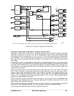
NOTE
Tables 8-32 through 8-36 provide detailed logic definitions for the inputs, outputs,
protection, and control elements. Only those inputs, logic blocks, virtual switches,
and outputs in use for the CDS240-MOTR-A-BE preprogrammed logic are
described in the following tables.
Table 8-32. CDS240-MOTR-A-BE Contact Input Logic
State Labels
Input Purpose Name
Label
Energized De-Energized
IN1
Optional input. Used for CT Input Circuit 1
Breaker status indication in SER reports. TRUE
when breaker closed.
BREAKER-1 CLOSED
OPEN
IN2
Speed switch, closed at reset. Used to block the
51S locked rotor protection (for high inertia
motors) during running.
SPEED-
SWITCH
RUNNING STOPPED
IN3
Emergency trip. This is an optional input.
EMERG-TRIP
TRIP
NORMAL
Table 8-33. CDS240-MOTR-A-BE Function Block Logic
Function Purpose
BESTlogic
Expression
Mode
Setting
87
Used for percent-restrained differential protection with high-speed
unrestrained instantaneous differential protection.
0 1
(enabled)
51P
51P is used for motor overload protection. Blocking during starting is
not required since this element is slower than the LR protection. It
serves as backup during starting.
0
G (Ground
Input)
51Q
51Q is used for unbalance protection (46).
0
1 (Circuit 1)
151P
The 151P element provides locked rotor protection for high inertia
motors. Blocked when low inertia is selected by Switch 243. If high
Inertia is selected, it is unblocked when starting as determined by
intermediate logic VO7.
/VO7+/243
1 (Circuit 1)
9365200990 Rev F
BE1-CDS240 Application
8-49
Summary of Contents for BE1-CDS240
Page 2: ......
Page 8: ...vi BE1 CDS240 Introduction 9365200990 Rev F This page intentionally left blank ...
Page 38: ...1 28 BE1 CDS240 General Information 9365200990 Rev F This page intentionally left blank ...
Page 40: ...ii BE1 CDS240 Quick Start 9365200990 Rev F This page intentionally left blank ...
Page 152: ...ii BE1 CDS240 Metering 9365200990 Rev F This page intentionally left blank ...
Page 226: ...iv BE1 CDS240 Application 9365200990 Rev F This page intentionally left blank ...
Page 286: ...ii BE1 CDS240 Security 9365200990 Rev F This page intentionally left blank ...
Page 290: ...9 4 BE1 CDS240 Security 9365200990 Rev F This page intentionally left blank ...
Page 292: ...ii BE1 CDS240 Human Machine Interface 9365200990 Rev F This page intentionally left blank ...
Page 306: ...10 14 BE1 CDS240 Human Machine Interface 9365200990 Rev F This page intentionally left blank ...
Page 308: ...ii BE1 CDS240 ASCII Command Interface 9365200990 Rev F This page intentionally left blank ...
Page 342: ...11 34 BE1 CDS240 ASCII Command Interface 9365200990 Rev F This page intentionally left blank ...
Page 349: ...Figure 12 5 Horizontal Rack Mount Front View 9365200990 Rev F BE1 CDS240 Installation 12 5 ...
Page 361: ...Figure 12 17 Typical DC Connection Diagrams 9365200990 Rev F BE1 CDS240 Installation 12 17 ...
Page 372: ...12 28 BE1 CDS240 Installation 9365200990 Rev F This page intentionally left blank ...
Page 468: ...13 92 BE1 CDS240 Testing and Maintenance 9365200990 Rev F This page intentionally left blank ...
Page 512: ...14 42 BE1 CDS240 BESTCOMS Software 9365200990 Rev F This page intentionally left blank ...
Page 544: ...ii BE1 CDS240 Terminal Communication 9365200990 Rev F This page intentionally left blank ...
Page 550: ...ii BE1 CDS240 Settings Calculations 9365200990 Rev F This page intentionally left blank ...
Page 578: ...D 28 BE1 CDS240 Settings Calculations 9365200990 Rev F This page intentionally left blank ...
Page 579: ......


