D2850-09.vsd
06-29-99
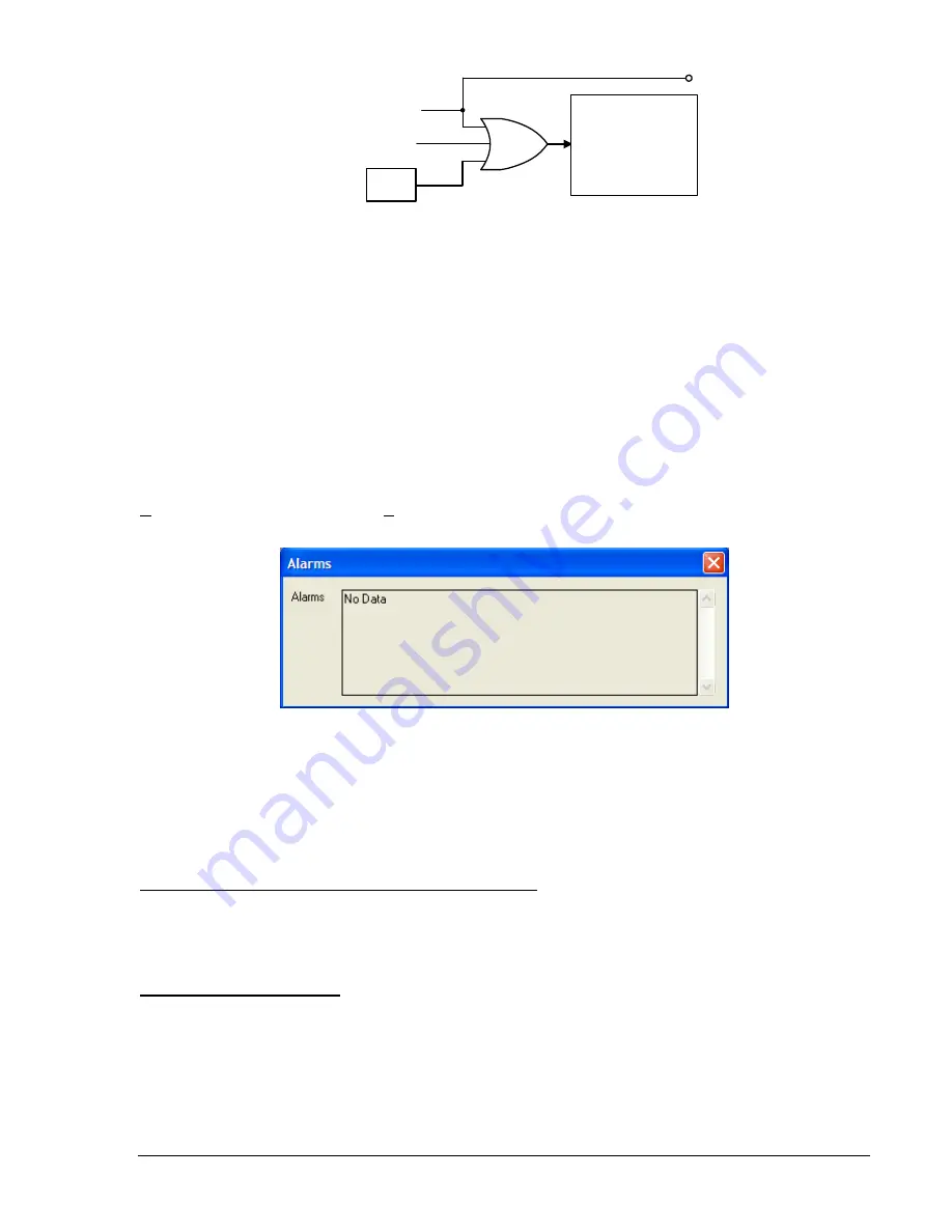
RA-MAJ=0
Logic
Alarm
Reset
Logic
RA-MIN=0
ARSTKEY
HMI RESET KEY
Figure 6-27. Alarm Reset Logic
The
Reset
key of the HMI is context sensitive. That is, the functionality depends upon what screen is
currently being displayed. BESTlogic variable ARSTKEY takes advantage of this to allow the front panel
Reset
key to be used in the programmable logic scheme when Alarm Screen 1.2, \STAT\ALARMS, is
active. An example of the use of this logic variable is to break the seal-in for a logic expression. The logic
expression can be programmed so that the seal-in function uses VO13, VO14, or VO15. If the virtual
output expression is included in one of the programmable alarm masks, the automatic display priority
logic will cause the display to go to Alarm Screen 1.2, \STAT\ALARMS. When the HMI
Reset
key is
pressed, the ARSTKEY logic variable is asserted and the logic expression seal-in is broken. See Section
8,
Application, Application Tips
, for more information. Pressing the HMI
Reset
key while the
Alarm
screen
is displayed, will clear any latched alarms that are not currently active. Refer to Table 6-21 for a list of
latching alarm points and self-clearing alarm points. Figure 6-27 shows the alarm reset logic.
After an operation, alarms information can be viewed using BESTCOMS. Select
Metering
from the
Reports
pull-down menu. From the
View
pull-down menu, select
Alarms Status
(Figure 6-28).
Figure 6-28. Alarms Status, Metering Screen
The RA (report alarms) command can be used to read detailed alarm reports and reset latched alarms.
Links between Programmable Alarms and BESTlogic
Several links between the programmable alarms and BESTlogic allow alarm functions to be used in the
logic scheme and programmable logic functions to be used in the alarm reporting function.
Programmable Alarms Controlled by BESTlogic Elements
Virtual Outputs VO13, VO14, and VO15 are driven by BESTlogic expressions and are available in the
programmable alarms function. These three virtual outputs have labels that can be assigned meaningful
names. Then, when a logic condition that is used for an alarm exists, the label will be reported in the
alarm reporting function.
Programmable Alarms Reset
Programmable alarms can be reset by any one of three methods:
The programmable alarms reset logic expression becomes TRUE.
Pressing the front panel
Reset
key when HMI Screen 1.2, \STAT\ALARMS is active.
By connecting the alarms reset logic in BESTCOMS. Alternately, this can be done using the SA-
RESET ASCII command.
9365200990 Rev F
BE1-CDS240 Reporting and Alarm Functions
6-43
Summary of Contents for BE1-CDS240
Page 2: ......
Page 8: ...vi BE1 CDS240 Introduction 9365200990 Rev F This page intentionally left blank ...
Page 38: ...1 28 BE1 CDS240 General Information 9365200990 Rev F This page intentionally left blank ...
Page 40: ...ii BE1 CDS240 Quick Start 9365200990 Rev F This page intentionally left blank ...
Page 152: ...ii BE1 CDS240 Metering 9365200990 Rev F This page intentionally left blank ...
Page 226: ...iv BE1 CDS240 Application 9365200990 Rev F This page intentionally left blank ...
Page 286: ...ii BE1 CDS240 Security 9365200990 Rev F This page intentionally left blank ...
Page 290: ...9 4 BE1 CDS240 Security 9365200990 Rev F This page intentionally left blank ...
Page 292: ...ii BE1 CDS240 Human Machine Interface 9365200990 Rev F This page intentionally left blank ...
Page 306: ...10 14 BE1 CDS240 Human Machine Interface 9365200990 Rev F This page intentionally left blank ...
Page 308: ...ii BE1 CDS240 ASCII Command Interface 9365200990 Rev F This page intentionally left blank ...
Page 342: ...11 34 BE1 CDS240 ASCII Command Interface 9365200990 Rev F This page intentionally left blank ...
Page 349: ...Figure 12 5 Horizontal Rack Mount Front View 9365200990 Rev F BE1 CDS240 Installation 12 5 ...
Page 361: ...Figure 12 17 Typical DC Connection Diagrams 9365200990 Rev F BE1 CDS240 Installation 12 17 ...
Page 372: ...12 28 BE1 CDS240 Installation 9365200990 Rev F This page intentionally left blank ...
Page 468: ...13 92 BE1 CDS240 Testing and Maintenance 9365200990 Rev F This page intentionally left blank ...
Page 512: ...14 42 BE1 CDS240 BESTCOMS Software 9365200990 Rev F This page intentionally left blank ...
Page 544: ...ii BE1 CDS240 Terminal Communication 9365200990 Rev F This page intentionally left blank ...
Page 550: ...ii BE1 CDS240 Settings Calculations 9365200990 Rev F This page intentionally left blank ...
Page 578: ...D 28 BE1 CDS240 Settings Calculations 9365200990 Rev F This page intentionally left blank ...
Page 579: ......


