


OPTO
OPTO
OPTO
D2850-06
04-29-99
9
Note: For clarity, multiple variables
going to the same OR Gate are shown
by a single line into the OR Gate.
50TN
Mode1
50TNT
50TNPU
5OTQ
Mode1
50TQT
50TQPU
BLK
BLK
8
VO11 PROT TRIP
VO12 PROT PU
VOA
Relay
Trouble
OUTA
Output
Logic
VO1
Motor
Trip
OUT1
Output
Logic
VO2
Not Used
OUT2
Output
Logic
VO3
Not Used
OUT3
Output
Logic
VO4
Overload
Alarm
OUT4
Output
Logic
VO5
Unbalance
Alarm
OUT5
Output
Logic
VO6
Not Used
Output
Logic
VO15
Unbalance
Alarm Point 23
OUT6
87
Mode1
87RT
87RPU
BLK
87UT
2NDHAR
5THHAR
143
Speed
Switch
Enable
143
IN1
Breaker1
Status
IN3 Emergency Trip
51Q
Mode1
51QT
51QPU
51P
Mode1
51PT
51PPU
BLK
BLK
151P
Mode1
151PT
151PPU
150TP
Mode1
150TPT
150TPPU
BLK
BLK
251P
Mode1
251PT
251PPU
BLK
VO14
Overload
Alarm Point 22
VO13
Emergency Trip
Alarm Point 21
HMI
TRSTKEY
ARSTKEY
VO9
Emergency Trip
Seal In
243
High/Low
Inertia Select
243
VO7
Starting
High Inertia
VO8
Starting
250TP
Mode1
250TPT
250TPPU
BLK
IN2
Speed Switch
Closed At Rest
50TP
Mode1
50TPT
50TPPU
BLK
LEGEND:
87 = Differential Fault Protection
50TN = BU Ground Fault Protection
50TQ = Loss Of Phase Protection
51Q = Unbalance Protection
51P = Overload Protection
151P = Locked Rotor (High Inertia)
150TP = Locked Rotor (Low Inertia)
251P = Jam Protection
50TP = Start Detection (High Inertia)
250TP = Start/Running Detection
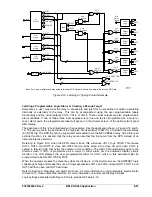
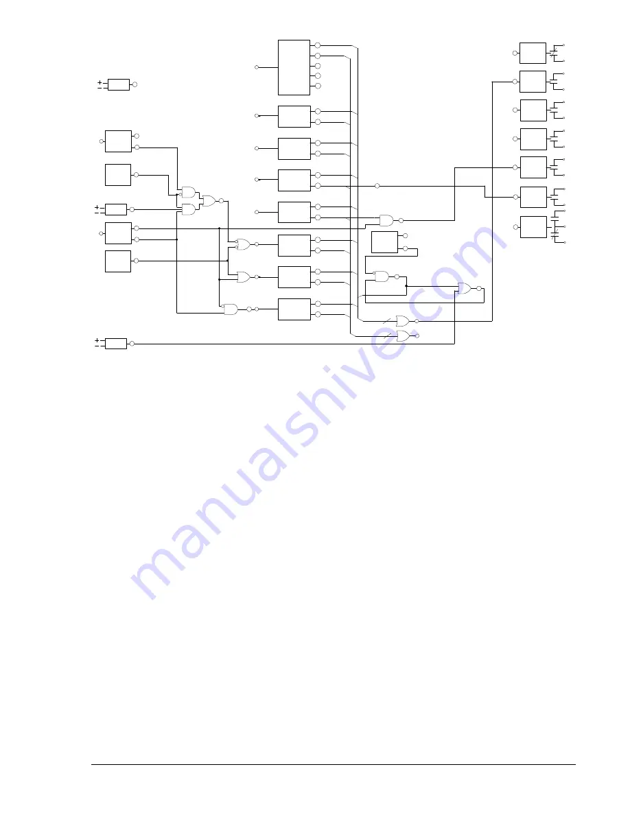
Figure 8-14. Typical Logic Diagram for CDS240-MOTR-A-BE
Protection Elements
Referring to Figure 8-13, the 87, 50/51, 150/151, and 250 protection elements are connected to CT Input
1, and the motor side of the 87 protection element is connected to Input 2. The 87, 50/51, 150/151, and
250 protection elements are logic enabled to provide a trip by the settings shown in Table 8-31.
Protection elements set at 0 are setting disabled, and will not provide a trip output even if logic enabled.
Typically, the 87 protection element provides high-speed, percent restrained, phase and ground
protection, for faults inside the differential zone. For the CDS240-MOTR-A-BE application shown in Figure
8-14, the percent-restrained differential protection function is the only function of the 87 protection
element required. Set the pickup of the 2
nd
, 5
th
, and 87U functions to 0 (setting disabled). The
unrestrained differential function has a setting only when the 2
nd
and 5
th
harmonic restraint functions are
set for transformer applications (refer to the discussion in
Overview Of Preprogrammed Logic Schemes
).
In the CDS240-MOTR-A-BE scheme, the 50TQ protection element is used for loss of phase detection,
the 51Q protection element is used for unbalance protection (46), and the 50TN protection element is
used for ground fault backup protection.
In the CDS240-MOTR-A-BE scheme, the 51P protection element is used for motor overload protection.
Blocking during starting is not required since this element is slower than the locked rotor protection. It also
serves as backup during starting. The 251P protection element is used to protect for a jam or stall
condition. It is blocked while the motor is starting as determined by VO8.
In the CDS240-MOTR-A-BE scheme, the 150TP protection element provides locked rotor protection for
low inertia motors. It is blocked when the motor is running (after the 250TP time setting expires) or when
Virtual Control Switch 243 is set to high inertia mode. The 151P protection element provides locked rotor
protection for high inertia motors. It is blocked when Virtual Control Switch 243 is set to low inertia mode.
9365200990 Rev F
BE1-CDS240 Application
8-47
Summary of Contents for BE1-CDS240
Page 2: ......
Page 8: ...vi BE1 CDS240 Introduction 9365200990 Rev F This page intentionally left blank ...
Page 38: ...1 28 BE1 CDS240 General Information 9365200990 Rev F This page intentionally left blank ...
Page 40: ...ii BE1 CDS240 Quick Start 9365200990 Rev F This page intentionally left blank ...
Page 152: ...ii BE1 CDS240 Metering 9365200990 Rev F This page intentionally left blank ...
Page 226: ...iv BE1 CDS240 Application 9365200990 Rev F This page intentionally left blank ...
Page 286: ...ii BE1 CDS240 Security 9365200990 Rev F This page intentionally left blank ...
Page 290: ...9 4 BE1 CDS240 Security 9365200990 Rev F This page intentionally left blank ...
Page 292: ...ii BE1 CDS240 Human Machine Interface 9365200990 Rev F This page intentionally left blank ...
Page 306: ...10 14 BE1 CDS240 Human Machine Interface 9365200990 Rev F This page intentionally left blank ...
Page 308: ...ii BE1 CDS240 ASCII Command Interface 9365200990 Rev F This page intentionally left blank ...
Page 342: ...11 34 BE1 CDS240 ASCII Command Interface 9365200990 Rev F This page intentionally left blank ...
Page 349: ...Figure 12 5 Horizontal Rack Mount Front View 9365200990 Rev F BE1 CDS240 Installation 12 5 ...
Page 361: ...Figure 12 17 Typical DC Connection Diagrams 9365200990 Rev F BE1 CDS240 Installation 12 17 ...
Page 372: ...12 28 BE1 CDS240 Installation 9365200990 Rev F This page intentionally left blank ...
Page 468: ...13 92 BE1 CDS240 Testing and Maintenance 9365200990 Rev F This page intentionally left blank ...
Page 512: ...14 42 BE1 CDS240 BESTCOMS Software 9365200990 Rev F This page intentionally left blank ...
Page 544: ...ii BE1 CDS240 Terminal Communication 9365200990 Rev F This page intentionally left blank ...
Page 550: ...ii BE1 CDS240 Settings Calculations 9365200990 Rev F This page intentionally left blank ...
Page 578: ...D 28 BE1 CDS240 Settings Calculations 9365200990 Rev F This page intentionally left blank ...
Page 579: ......


