


8-24
BE1-CDS240 Application
9365200990 Rev F
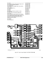
CDS240-TXBU-B-BE (TRANSFORMER DIFF WITH BACKUP) LOGIC SCHEME
The Transformer With Backup (CDS240-TXBU-B-BE) scheme was designed to provide high-speed phase
and ground fault protection for a two-winding transformer and definite time backup protection for the
associated low-side bus (similar to the BE1-851 BUS and BACKUP Logic Scheme). Figure 8-7 shows the
interconnection of the BE1-851 or BE1-951 relays providing bus and feeder protection with a BE1-
CDS240 (CDS240-TXBU-B-BE) providing backup transformer protection. The CDS240-TXBU-B-BE
scheme also includes a low-side breaker BF (breaker failure) protection element with fast current reset.
Current and contact supervised external breaker failure initiates (BFI) are included for the low-side
breaker BF element. Virtual control switch logic is used for local or remote (SCADA) control and can be
used to replace the equivalent panel control switch. See the paragraphs on
BUS WITH BACKUP
SCHEME
, in this section for an interconnection of BE1-851 or BE1-951 relays providing feeder protection
with BE1-CDS240 relays providing bus protection (CDS240-BSBU-A-BE) and transformer protection
(CDS240-TXBU-B-BE).
The control switch elements are referred to as virtual because they have no physical form, they exist only
in logic form, and they can only be operated via the ASCII command interface or the front panel HMI. The
Virtual 101 Switch is used to trip and close the transformer low-side breaker, and 743 are used to select
test mode enable. The user may choose to eliminate the use of external switches, as the virtual switches
are fully functional equivalents of their physical counterparts.
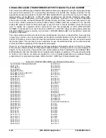
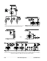
Figure 8-7 is a logic drawing that represents the logic settings and equations shown in Table 8-19, Figure
8-8 is a Device Interconnection for Integrated Protection System, and Figure 8-9 is a one-line drawing. In
Table 8-19, the user can see the protection and control elements that are enabled for the CDS240-TXBU-
B-BE application and how the elements are logically wired together (equations). If the user should decide
to build on this scheme, all elements required for a more detailed application are available through
programming. For programming details, refer to Section 7,
BESTlogic Programmable Logic.
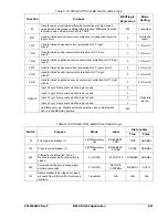
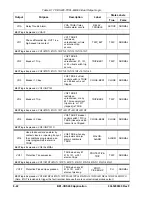
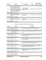
Table 8-19. CDS240-TXBU-B-BE Logic Settings and Equations
SL-N=CDS240-TXBU-B-BE,BASLER
SL-87=1,43
SL-87ND=0,0
SL-187ND=0,0
SL-50BF=0,0,0,0,0
SL-150BF=1,VO10,0,IN2,VO15
SL-250BF=0,0,0,0,0
SL-350BF=0,0,0,0,0
SL-50TP=2,0
SL-50TN=2,0
SL-50TQ=2,0
SL-150TP=0,0
SL-150TN=0,0
SL-150TQ=0,0
SL-250TP=2,0
SL-250TN=2,0
SL-250TQ=2,0
SL-350TP=0,0
SL-350TN=0,0
SL-350TQ=0,0
SL-450TP=0,0
SL-450TN=0,0
SL-550TP=0,0
SL-650TP=0,0
SL-750TP=0,0
SL-51P=0,0
SL-51N=G,0
SL-51Q=0,0
SL-151P=1,0
SL-151N=1,0
SL-151Q=1,0
SL-251P=2,0
SL-251N=2,0
SL-251Q=2,0
SL-351P=0,0
SL-351N=0,0
SL-351Q=0,0
SL-451N=0,0
SL-24=0,0
SL-27P=0,0
SL-127P=0,0
SL-47=0,0
SL-59P=0,0
SL-59X=0,0
SL-159P=0,0
SL-81=0,0
SL-181=0,0
SL-281=0,0
SL-381=0,0
SL-481=0,0
SL-581=0,0
SL-62=1,VO9,VO15
SL-162=0,0,0
SL-262=0,0,0
SL-362=0,0,0
SL-GROUP=2,/IN5,0,0,0,0
SL-43=2
SL-143=0
SL-243=0
SL-343=0
SL-443=0
SL-543=0
SL-643=0
SL-743=2
SL-101=1
SL-1101=0
SL-2101=0
SL-3101=0
Summary of Contents for BE1-CDS240
Page 2: ......
Page 8: ...vi BE1 CDS240 Introduction 9365200990 Rev F This page intentionally left blank ...
Page 38: ...1 28 BE1 CDS240 General Information 9365200990 Rev F This page intentionally left blank ...
Page 40: ...ii BE1 CDS240 Quick Start 9365200990 Rev F This page intentionally left blank ...
Page 152: ...ii BE1 CDS240 Metering 9365200990 Rev F This page intentionally left blank ...
Page 226: ...iv BE1 CDS240 Application 9365200990 Rev F This page intentionally left blank ...
Page 286: ...ii BE1 CDS240 Security 9365200990 Rev F This page intentionally left blank ...
Page 290: ...9 4 BE1 CDS240 Security 9365200990 Rev F This page intentionally left blank ...
Page 292: ...ii BE1 CDS240 Human Machine Interface 9365200990 Rev F This page intentionally left blank ...
Page 306: ...10 14 BE1 CDS240 Human Machine Interface 9365200990 Rev F This page intentionally left blank ...
Page 308: ...ii BE1 CDS240 ASCII Command Interface 9365200990 Rev F This page intentionally left blank ...
Page 342: ...11 34 BE1 CDS240 ASCII Command Interface 9365200990 Rev F This page intentionally left blank ...
Page 349: ...Figure 12 5 Horizontal Rack Mount Front View 9365200990 Rev F BE1 CDS240 Installation 12 5 ...
Page 361: ...Figure 12 17 Typical DC Connection Diagrams 9365200990 Rev F BE1 CDS240 Installation 12 17 ...
Page 372: ...12 28 BE1 CDS240 Installation 9365200990 Rev F This page intentionally left blank ...
Page 468: ...13 92 BE1 CDS240 Testing and Maintenance 9365200990 Rev F This page intentionally left blank ...
Page 512: ...14 42 BE1 CDS240 BESTCOMS Software 9365200990 Rev F This page intentionally left blank ...
Page 544: ...ii BE1 CDS240 Terminal Communication 9365200990 Rev F This page intentionally left blank ...
Page 550: ...ii BE1 CDS240 Settings Calculations 9365200990 Rev F This page intentionally left blank ...
Page 578: ...D 28 BE1 CDS240 Settings Calculations 9365200990 Rev F This page intentionally left blank ...
Page 579: ......


