


Problem 2: Measured Current Magnitude Mismatch
General
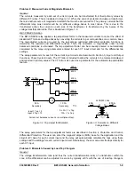
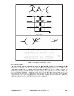
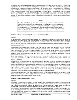
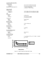
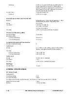
The currents measured by each set of current inputs can be transformed from their primary values by
different CT ratios. This is illustrated in Figure 1-2. When the zone of protection includes a transformer,
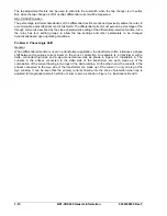
there is another source of magnitude mismatch that must be accounted for. The primary currents that the
differential relay must monitor will be on different voltage bases in most cases. This is due to the
transformer action; the current on each side of the transformer is transformed by the inverse of the
voltage transformation ratio. This is illustrated in Figure 1-3.
BE1-CDS240 Solution
The BE1-CDS240 relay applies a tap adjustment factor to the measured currents to cancel the effect of
dissimilar CT ratio and voltage bases by converting the currents to per unit quantities on a common base.
The tap-adjusted currents are used by the percentage restrained differential protection functions to
determine the restraint and differential currents. Thus, the mismatch in magnitudes under normal
balanced conditions is eliminated. The tap adjustment factor can be manually entered or automatically
calculated by the relay using parameters entered for each CT input circuit and for the differential tap
settings.
The setup parameters for each of the current input circuits are described in Section 3,
Input and Output
Functions, Power System Inputs
. The CT ratio is included to allow the currents to be metered, displayed,
and reported in primary values. The CT ratio is also used as a parameter for the automatic tap calculation
feature.
D2837-18
12-14-98
600:5
400A
600:5
400A
600:5
400A
CDS
1200:5
1200A
5.0 A
Secondary
10.0 A
Secondary
Input 1 Tap = 5
Input 2 Tap = 10
So 5A = 1 x Tap
10A = 1 x Tap
Current-out balances current-in (in multiples of tap).
9365200990 Rev F
BE1-CDS240 General Information
1-9
40A
D2837-17.vsd
12-14-98
2400/240 Volts
H
1
H
0
400A
X
1
X
0
Figure 1-2. Tap Adjust for Mismatch
Figure 1-3. Currents on Different
Voltage Bases
The setup parameters for the tap adjustment factor are described in Section 4,
Protection and Control,
Differential Protection
. The user can enter the megavolt ampere (MVA) base for the application and the
kilovolt (kV) base for each current input and the relay will automatically calculate the taps using these
settings and the settings for each current input circuit. Alternatively, the user can enter the taps directly for
each CT input.
Problem 3: Mismatch Caused by Load Tap Changers
General
The voltage transformation ratio (and thus the current transformation ratio) of a transformer within the
zone of the differential can be adjusted in service by typically ±10% with the use of load tap changers.
Summary of Contents for BE1-CDS240
Page 2: ......
Page 8: ...vi BE1 CDS240 Introduction 9365200990 Rev F This page intentionally left blank ...
Page 38: ...1 28 BE1 CDS240 General Information 9365200990 Rev F This page intentionally left blank ...
Page 40: ...ii BE1 CDS240 Quick Start 9365200990 Rev F This page intentionally left blank ...
Page 152: ...ii BE1 CDS240 Metering 9365200990 Rev F This page intentionally left blank ...
Page 226: ...iv BE1 CDS240 Application 9365200990 Rev F This page intentionally left blank ...
Page 286: ...ii BE1 CDS240 Security 9365200990 Rev F This page intentionally left blank ...
Page 290: ...9 4 BE1 CDS240 Security 9365200990 Rev F This page intentionally left blank ...
Page 292: ...ii BE1 CDS240 Human Machine Interface 9365200990 Rev F This page intentionally left blank ...
Page 306: ...10 14 BE1 CDS240 Human Machine Interface 9365200990 Rev F This page intentionally left blank ...
Page 308: ...ii BE1 CDS240 ASCII Command Interface 9365200990 Rev F This page intentionally left blank ...
Page 342: ...11 34 BE1 CDS240 ASCII Command Interface 9365200990 Rev F This page intentionally left blank ...
Page 349: ...Figure 12 5 Horizontal Rack Mount Front View 9365200990 Rev F BE1 CDS240 Installation 12 5 ...
Page 361: ...Figure 12 17 Typical DC Connection Diagrams 9365200990 Rev F BE1 CDS240 Installation 12 17 ...
Page 372: ...12 28 BE1 CDS240 Installation 9365200990 Rev F This page intentionally left blank ...
Page 468: ...13 92 BE1 CDS240 Testing and Maintenance 9365200990 Rev F This page intentionally left blank ...
Page 512: ...14 42 BE1 CDS240 BESTCOMS Software 9365200990 Rev F This page intentionally left blank ...
Page 544: ...ii BE1 CDS240 Terminal Communication 9365200990 Rev F This page intentionally left blank ...
Page 550: ...ii BE1 CDS240 Settings Calculations 9365200990 Rev F This page intentionally left blank ...
Page 578: ...D 28 BE1 CDS240 Settings Calculations 9365200990 Rev F This page intentionally left blank ...
Page 579: ......


