


13-62
BE1-CDS240 Testing and Maintenance
9365200990 Rev F
To change from Setting Group 0 to Setting Group 1, execute the following commands:
CS-GROUP=1 Select Setting Group 1
CO-GROUP=1 Execute Setting Group 1
Using the basic information in Table 13-50, program the pickup of the elements for Setting
Group 1 and, optionally, proceed with the testing.
Timing Verification (51/151/251/351/451)
Purpose:
To verify the accuracy of the timing operation of the 51/151/251/351/451 elements.
Reference Commands:
SL-51/151/251.351/451, S<n>-51
Step 1:
Connect a current source to Terminals A3* and A4 (A-phase Input 1).
Step 2:
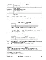
To initially prepare the 51/151/251.351/451 elements for testing, send the commands in Table
13-55 to the relay.
Table 13-55. 51/151/251 Overcurrent Timing Test Commands
Command Purpose
A= Gain
access.
SL-N=NONE
Zero out custom logic settings/overwrite with logic =
None settings.
Y Confirm
overwrite.
SL-N= 51
Name custom logic for this test.
SL-51=1,0
Enables 51P/51N/51Q, CT Input 1.
SL-VO1=51PT
Enables OUT1 to close for 50P trip.
SL-VO2=51NT
Enables OUT2 to close for 51N trip.
SL-VO3=51QT
Enables OUT3 to close for 51Q trip.
SG-CT1=1,WYE,NA,0 Input
1
ctr = 1, ct = wye, xfmr = n/a, no ground source.
SG-TRIGGER=51PT+ 51NT+51QT,51PPU+
51NPU+51QPU,0
Enable 51PT+51NT+51QT to log targets and trigger
fault recording.
E Exit.
Y Save
settings.
Step 3:
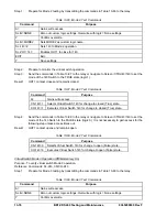
Transmit to the relay the appropriate row of the setting commands S0-51P from Table 13-56.
Using the HMI, you may also go to the front panel interface Screen \PROT\SG0\50T\50T and
edit the 51P, 51N, and 51Q settings.
Table 13-56. Time Overcurrent 51 Element Test Settings
Sensing Input Type
Phase
Neutral
Negative-Sequence
1 A
S0-51P=1.0,0.5,I2
S0-51N=1.0,0.5,I2 S0-51Q=0.33,0.5,I2
5 A
S0-51P=5.0,0.5,I2
S0-51N=5.0,0.5,I2 S0-51Q=1.67,0.5,I2
Note: See Sidebar 13-10 for more information on negative-sequence pickup.
Step 4:
Using the values listed in Table 13-57, apply the current listed to the A phase current input and
measure the time between the application of current and the time it takes for the relay outputs
OUT1, OUT2, and OUT3 to close. Verify that the relay performs with the specified limits. An
ohmmeter or continuity tester may be used to monitor the output contacts status.
Summary of Contents for BE1-CDS240
Page 2: ......
Page 8: ...vi BE1 CDS240 Introduction 9365200990 Rev F This page intentionally left blank ...
Page 38: ...1 28 BE1 CDS240 General Information 9365200990 Rev F This page intentionally left blank ...
Page 40: ...ii BE1 CDS240 Quick Start 9365200990 Rev F This page intentionally left blank ...
Page 152: ...ii BE1 CDS240 Metering 9365200990 Rev F This page intentionally left blank ...
Page 226: ...iv BE1 CDS240 Application 9365200990 Rev F This page intentionally left blank ...
Page 286: ...ii BE1 CDS240 Security 9365200990 Rev F This page intentionally left blank ...
Page 290: ...9 4 BE1 CDS240 Security 9365200990 Rev F This page intentionally left blank ...
Page 292: ...ii BE1 CDS240 Human Machine Interface 9365200990 Rev F This page intentionally left blank ...
Page 306: ...10 14 BE1 CDS240 Human Machine Interface 9365200990 Rev F This page intentionally left blank ...
Page 308: ...ii BE1 CDS240 ASCII Command Interface 9365200990 Rev F This page intentionally left blank ...
Page 342: ...11 34 BE1 CDS240 ASCII Command Interface 9365200990 Rev F This page intentionally left blank ...
Page 349: ...Figure 12 5 Horizontal Rack Mount Front View 9365200990 Rev F BE1 CDS240 Installation 12 5 ...
Page 361: ...Figure 12 17 Typical DC Connection Diagrams 9365200990 Rev F BE1 CDS240 Installation 12 17 ...
Page 372: ...12 28 BE1 CDS240 Installation 9365200990 Rev F This page intentionally left blank ...
Page 468: ...13 92 BE1 CDS240 Testing and Maintenance 9365200990 Rev F This page intentionally left blank ...
Page 512: ...14 42 BE1 CDS240 BESTCOMS Software 9365200990 Rev F This page intentionally left blank ...
Page 544: ...ii BE1 CDS240 Terminal Communication 9365200990 Rev F This page intentionally left blank ...
Page 550: ...ii BE1 CDS240 Settings Calculations 9365200990 Rev F This page intentionally left blank ...
Page 578: ...D 28 BE1 CDS240 Settings Calculations 9365200990 Rev F This page intentionally left blank ...
Page 579: ......


