


The
BLK
(block) input is used to disable protection. A BESTlogic expression is used to define how the
BLK input functions. When this expression is TRUE, the element is disabled by forcing the outputs to
logic 0 and resetting the timer. This feature functions in a similar way to the torque control contact of an
electromechanical relay.
An element is enabled or disabled by the
Mode
input. Two mode options are possible.
Mode 0
disables
protection and
Mode 1
enables the element to monitor the frequency on VTP input. Security of your load-
shedding scheme can be enhanced by monitoring two independent VT circuits. See Section 8,
Application,
for more information. More information about logic mode selections is provided in the
following
BESTlogic Settings for Underfrequency and Overfrequency Elements
paragraphs. Pickup
settings define the frequency setpoint and time delay, and program the element for underfrequency or
overfrequency protection. The frequency setpoint defines the value of frequency that will initiate action by
an element. The time delay setting determines how long it takes the trip output to become TRUE once the
measured frequency reaches the frequency setpoint. If three consecutive cycles of the measured
frequency have either decreased (81U) below or increased (81O) above the pickup threshold, and the
timer has timed out, then the 81T will trip. If the timer has not timed out and the frequency remains in the
pickup range for the remainder of the time delay, the 81T will trip. If the monitored voltage decreases
below the user-defined setpoint, frequency protection is inhibited.
If the target is enabled for the element, the target reporting function will record a target for the appropriate
phase when the protective function trip output is TRUE
and
the fault recording function trip logic
expression is TRUE. See Section 6,
Reporting and Alarm Functions, Fault Reporting,
for more
information about target reporting.
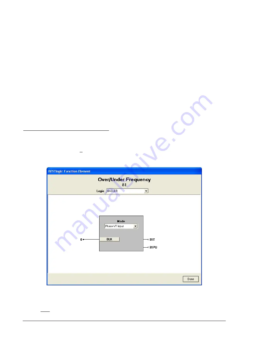
BESTlogic Settings for Over/Underfrequency
BESTlogic settings are made from the
BESTlogic Function Element
screen in BESTCOMS. Figure 4-47
illustrates the BESTCOMS screen used to select BESTlogic settings for the Over/Underfrequency
element. To open the
BESTlogic Function Element
screen for Over/Underfrequency element, select
Voltage Protection
from the
Screens
pull-down menu and select the
INH/81/181/281/381/481/581
tab.
Then select the
BESTlogic
button for the element to be programmed. Alternately, settings may be made
using the SL-<x>81 ASCII command.
Figure 4-47. BESTlogic Function Element Screen, 81
At the top center of the
BESTlogic Function Element
screen is a pull-down menu labeled
Logic
. This
menu allows viewing of the BESTlogic settings for each preprogrammed logic scheme. A custom logic
scheme must be created and selected in the
Logic
pull-down menu at the top of the screen before
BESTlogic settings can be changed. See Section 7,
BESTlogic Programmable Logic
. Enable the
4-52
BE1-CDS240 Protection and Control
9365200990 Rev F
Summary of Contents for BE1-CDS240
Page 2: ......
Page 8: ...vi BE1 CDS240 Introduction 9365200990 Rev F This page intentionally left blank ...
Page 38: ...1 28 BE1 CDS240 General Information 9365200990 Rev F This page intentionally left blank ...
Page 40: ...ii BE1 CDS240 Quick Start 9365200990 Rev F This page intentionally left blank ...
Page 152: ...ii BE1 CDS240 Metering 9365200990 Rev F This page intentionally left blank ...
Page 226: ...iv BE1 CDS240 Application 9365200990 Rev F This page intentionally left blank ...
Page 286: ...ii BE1 CDS240 Security 9365200990 Rev F This page intentionally left blank ...
Page 290: ...9 4 BE1 CDS240 Security 9365200990 Rev F This page intentionally left blank ...
Page 292: ...ii BE1 CDS240 Human Machine Interface 9365200990 Rev F This page intentionally left blank ...
Page 306: ...10 14 BE1 CDS240 Human Machine Interface 9365200990 Rev F This page intentionally left blank ...
Page 308: ...ii BE1 CDS240 ASCII Command Interface 9365200990 Rev F This page intentionally left blank ...
Page 342: ...11 34 BE1 CDS240 ASCII Command Interface 9365200990 Rev F This page intentionally left blank ...
Page 349: ...Figure 12 5 Horizontal Rack Mount Front View 9365200990 Rev F BE1 CDS240 Installation 12 5 ...
Page 361: ...Figure 12 17 Typical DC Connection Diagrams 9365200990 Rev F BE1 CDS240 Installation 12 17 ...
Page 372: ...12 28 BE1 CDS240 Installation 9365200990 Rev F This page intentionally left blank ...
Page 468: ...13 92 BE1 CDS240 Testing and Maintenance 9365200990 Rev F This page intentionally left blank ...
Page 512: ...14 42 BE1 CDS240 BESTCOMS Software 9365200990 Rev F This page intentionally left blank ...
Page 544: ...ii BE1 CDS240 Terminal Communication 9365200990 Rev F This page intentionally left blank ...
Page 550: ...ii BE1 CDS240 Settings Calculations 9365200990 Rev F This page intentionally left blank ...
Page 578: ...D 28 BE1 CDS240 Settings Calculations 9365200990 Rev F This page intentionally left blank ...
Page 579: ......


