


13-66
BE1-CDS240 Testing and Maintenance
9365200990 Rev F
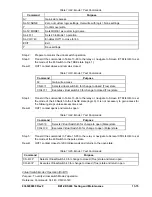
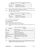
Step 1: Using Table 13-63 as a guide, transmit the setting commands to the relay.
Table 13-63. V/Hz Reset Time Pickup Settings
Settings
Purpose
S0-24=2.1,0.5,0.2,2.0
Sets 24 PU at 1.05% of nominal (2.10 V/Hz), Trip Time Dial = 0.5, Reset Time
Dial =0.2, time curve exponent = 2.
Step 2: Connect a 120 Vac, three-phase, 50 or 60-hertz voltage source (depending on user’s nominal
frequency) to Terminals B9 (A-phase), B10 (B-phase), B11 (C-phase), and B12 (neutral).
Refer to Figure 13-1 for terminal locations.
Step 3: Apply A-phase voltage at nominal frequency and a value of voltage that equals the V/Hz % of
nominal shown in Table 13-64. Measure the time between the application of voltage and the
closure of OUT1 (12.5 seconds). Remove the test voltage and reapply after 5 seconds has
elapsed.
With a Reset Time Dial setting of 0.2, the total time to reset, after trip is removed, will be
approximately 10 seconds. (See Section 4,
Protection and Control, Voltage Protection
, for
more details.) Reapplying the test voltage after 5 seconds will yield a trip time of approximately
½ its original value or 6.25 seconds for Trip Time Dial 0.5. This verifies that the reset time
delay is working.
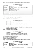
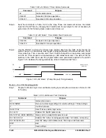
Table 13-64. V/Hz Reset Time
Percent of Nominal V/Hz
Time Dial 0.5
Time Dial 1.0
Time Dial 2.0
120%
12.5 seconds
25 seconds
50 seconds
Step 4: Repeat Step 3 for Trip Time Dial 1.0 and 2.0 (½ trip time is approximately 12.5 seconds for
Time Dial 1.0, and 25 seconds for Time Dial 2.0. (Still reapply voltage after 5 seconds as reset
time dial is still 0.2.)
Step 5: (Optional.) Repeat Steps 2 through 4 for the B-phase and C-phase voltage inputs.
Step 6: (Optional.) Repeat Steps 2 through 5 for Setting Group 1.
Overexcitation, Volts/Hertz Definite Time (24D)Trip Time Verification
The following test uses the (M-1)^2 time curve.
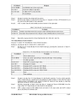
Step 1: Using Table 13-65 as a guide, transmit the setting commands to the relay.
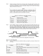
Table 13-65. Definite Time V/Hz Trip Time Settings
Settings
Purpose
S0-24D= 2.36,50ms,0.0, 50ms
Set the first 24 definite pickup at 118% of nominal (2.36 V/Hz) and
definite time delay at minimum. Set second pickup at 0 and time
delay at minimum.
Step 2: Connect a 120 Vac, three-phase, 50 or 60-hertz voltage source (depending on user’s nominal
frequency) to Terminals B9 (A-phase), B10 (B-phase), B11 (C-phase), and B12 (neutral).
Refer to Figure 13-1 for terminal locations.
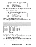
Step 3: Definite timing tests are based on % of nominal Volts/Hertz (1 PU value). Apply A-phase
voltage at nominal frequency and a value of voltage that equals the V/Hz % of nominal shown
in Table 13-66 (118% or 2.36 V/Hz)
.
Measure the time between the application of voltage and
the closure of OUT1. Verify that the relay operates 0.5% or 1 cycle, whichever is
greater, for the TD settings shown in Table 13-66.
Summary of Contents for BE1-CDS240
Page 2: ......
Page 8: ...vi BE1 CDS240 Introduction 9365200990 Rev F This page intentionally left blank ...
Page 38: ...1 28 BE1 CDS240 General Information 9365200990 Rev F This page intentionally left blank ...
Page 40: ...ii BE1 CDS240 Quick Start 9365200990 Rev F This page intentionally left blank ...
Page 152: ...ii BE1 CDS240 Metering 9365200990 Rev F This page intentionally left blank ...
Page 226: ...iv BE1 CDS240 Application 9365200990 Rev F This page intentionally left blank ...
Page 286: ...ii BE1 CDS240 Security 9365200990 Rev F This page intentionally left blank ...
Page 290: ...9 4 BE1 CDS240 Security 9365200990 Rev F This page intentionally left blank ...
Page 292: ...ii BE1 CDS240 Human Machine Interface 9365200990 Rev F This page intentionally left blank ...
Page 306: ...10 14 BE1 CDS240 Human Machine Interface 9365200990 Rev F This page intentionally left blank ...
Page 308: ...ii BE1 CDS240 ASCII Command Interface 9365200990 Rev F This page intentionally left blank ...
Page 342: ...11 34 BE1 CDS240 ASCII Command Interface 9365200990 Rev F This page intentionally left blank ...
Page 349: ...Figure 12 5 Horizontal Rack Mount Front View 9365200990 Rev F BE1 CDS240 Installation 12 5 ...
Page 361: ...Figure 12 17 Typical DC Connection Diagrams 9365200990 Rev F BE1 CDS240 Installation 12 17 ...
Page 372: ...12 28 BE1 CDS240 Installation 9365200990 Rev F This page intentionally left blank ...
Page 468: ...13 92 BE1 CDS240 Testing and Maintenance 9365200990 Rev F This page intentionally left blank ...
Page 512: ...14 42 BE1 CDS240 BESTCOMS Software 9365200990 Rev F This page intentionally left blank ...
Page 544: ...ii BE1 CDS240 Terminal Communication 9365200990 Rev F This page intentionally left blank ...
Page 550: ...ii BE1 CDS240 Settings Calculations 9365200990 Rev F This page intentionally left blank ...
Page 578: ...D 28 BE1 CDS240 Settings Calculations 9365200990 Rev F This page intentionally left blank ...
Page 579: ......


