


4. REPORTS. Display and resetting of report information such as time and date, demand registers,
breaker duty statistics, etc.
5. PROTECTION. Display and setting of protective function setting parameters such as logic
scheme, pickups, time delays, etc.
6. GENERAL SETTINGS. Display and setting of non-protective function setting parameters such as
communications, LCD contrast, and CT ratio.
Each screen in the menu tree displays the path in the upper left hand corner of the screen. Additionally,
each screen is assigned a number in the HMI section. The path indicates the branch and level in the
menu tree structure. This path should help you to keep track of where you are when you leave the menu
tree top level. You scroll through each level of the menu tree by using the right and left scrolling
pushbuttons. To go to a level of detail, you use the down scrolling pushbutton. Each time you go to a
lower level in the menu tree, another string is added to the path and separated by a backslash.
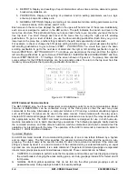
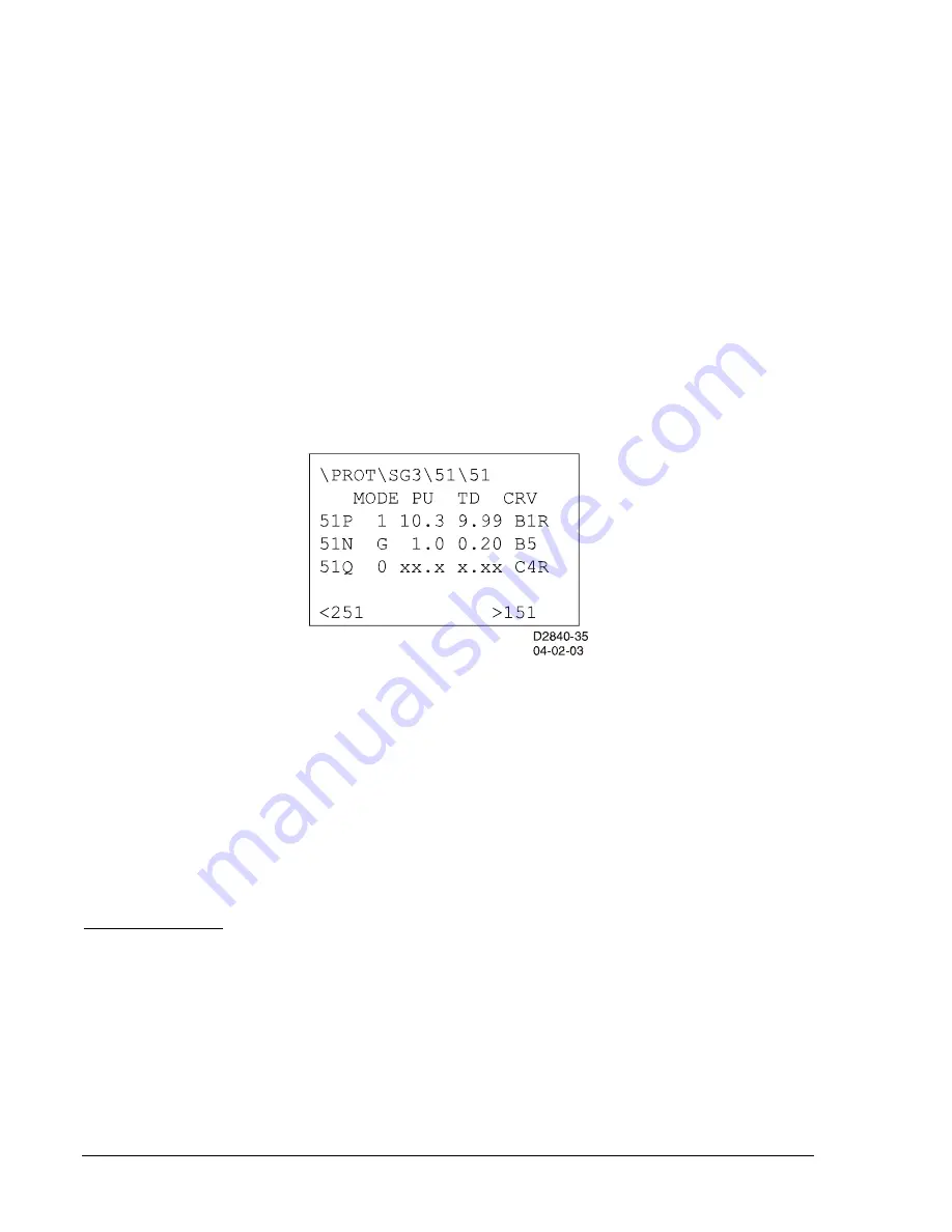
For example, to check or change the 51N pickup setting in Setting Group 3, you would press the right or
left scrolling pushbuttons to get to Screen \PROT -
PROTECTION
. You would then press the down
scrolling pushbutton to get to the next level of detail and the right or left scrolling pushbutton to get to
Screen \PROT\SG3 -
SETTING GROUP 3
. To continue, you would press the down and then the right or
left scrolling pushbuttons to get to Screen \PROT\SG3\51
INVERSE TIME OVERCURRENT
and then
Screen \PROT\SG3\51\51 - 51 Settings. On the screen shown in Figure 2-2, the pickup, time dial and
curve settings for the 51P/N/Q functions can be read and/or edited. To return to the top level from this
location, you would press the
Up
scrolling pushbutton three times.
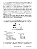
Figure 2-2. 51 HMI Screen
ASCII Command Communications
The BE1-CDS240 relay has three independent communications ports for serial communications.
Basler
Terminal
in BESTCOMS can be connected to any of the three ports so that the user may send
commands to the relay. Alternatively, a computer terminal or PC running a terminal emulation program
such as Windows
Terminal can be used in the same manner. Communication with the relay uses a
simple ASCII command language. When a command is entered via a serial port, the relay responds with
the appropriate action. The ASCII command communications is designed for use in both human-to-
machine interactions and in batch download type operations. The following paragraphs briefly describe
the command structure and then discuss human-to-machine interactions and batch command text file
operations for interacting with the relay. The operation of the ASCII commands is described in detail in
Section 11,
ASCII Command Interface
.
Command Structure
An ASCII command consists of a command string made up of one or two letters followed by a hyphen
and an object name. The first letter specifies the general command function and the second a sub-
grouping. The object name is the specific function for which the command is intended. If the command
string is entered by itself, it is a read command. If the command string is entered followed by an equal
sign and one or more parameters, it is a write command. The general command groupings are organized
into six major groups plus several miscellaneous commands. These commands are as follows:
C
CONTROL. Commands to perform select before operate control actions such as tripping and closing
the circuit breaker, changing the active setting group, etc. Sub-groupings include S for Select and O
for Operate.
G GLOBAL. Perform global operations that do not fall into the other general groupings such as
password security. Sub-groupings include S for security settings.
2-4
BE1-CDS240 Quick Start
9365200990 Rev F
Summary of Contents for BE1-CDS240
Page 2: ......
Page 8: ...vi BE1 CDS240 Introduction 9365200990 Rev F This page intentionally left blank ...
Page 38: ...1 28 BE1 CDS240 General Information 9365200990 Rev F This page intentionally left blank ...
Page 40: ...ii BE1 CDS240 Quick Start 9365200990 Rev F This page intentionally left blank ...
Page 152: ...ii BE1 CDS240 Metering 9365200990 Rev F This page intentionally left blank ...
Page 226: ...iv BE1 CDS240 Application 9365200990 Rev F This page intentionally left blank ...
Page 286: ...ii BE1 CDS240 Security 9365200990 Rev F This page intentionally left blank ...
Page 290: ...9 4 BE1 CDS240 Security 9365200990 Rev F This page intentionally left blank ...
Page 292: ...ii BE1 CDS240 Human Machine Interface 9365200990 Rev F This page intentionally left blank ...
Page 306: ...10 14 BE1 CDS240 Human Machine Interface 9365200990 Rev F This page intentionally left blank ...
Page 308: ...ii BE1 CDS240 ASCII Command Interface 9365200990 Rev F This page intentionally left blank ...
Page 342: ...11 34 BE1 CDS240 ASCII Command Interface 9365200990 Rev F This page intentionally left blank ...
Page 349: ...Figure 12 5 Horizontal Rack Mount Front View 9365200990 Rev F BE1 CDS240 Installation 12 5 ...
Page 361: ...Figure 12 17 Typical DC Connection Diagrams 9365200990 Rev F BE1 CDS240 Installation 12 17 ...
Page 372: ...12 28 BE1 CDS240 Installation 9365200990 Rev F This page intentionally left blank ...
Page 468: ...13 92 BE1 CDS240 Testing and Maintenance 9365200990 Rev F This page intentionally left blank ...
Page 512: ...14 42 BE1 CDS240 BESTCOMS Software 9365200990 Rev F This page intentionally left blank ...
Page 544: ...ii BE1 CDS240 Terminal Communication 9365200990 Rev F This page intentionally left blank ...
Page 550: ...ii BE1 CDS240 Settings Calculations 9365200990 Rev F This page intentionally left blank ...
Page 578: ...D 28 BE1 CDS240 Settings Calculations 9365200990 Rev F This page intentionally left blank ...
Page 579: ......


