


4-54
BE1-CDS240 Protection and Control
9365200990 Rev F
Beside the
Logic
pull-down menu is a pull-down menu labeled
Settings
. The Settings menu is used to
select the setting group that the element's settings apply to.
Over/Underfrequency protection can be inhibited when the monitored voltage decreases below a user-
defined level. The undervoltage inhibit level is set through BESTCOMS. Alternately, it can be set using
the S<g>-<x>81INH command where x equals nothing or one through five. Settings can also be made
using the optional HMI Screen 5.#.10.3, \PROT\SG#\81\SETTINGS. The voltage inhibit setting unit of
measure depends upon the VTP and VTX connection settings. For 4-wire or PN connections, it is Sec
VPN. For 3-wire or PP connections, it is Sec. VPP.
Table 4-29 summarizes the operating settings for Over/Underfrequency.
Table 4-29. Operating Settings for Over/Underfrequency
Setting Range
Increment
Unit of Measure
Default
Pickup
40 to 70, 0 = Disabled
0.01
Hertz
0
0 to 999 milliseconds
1
Milliseconds
0.1 for 0.1 to 9.9
Seconds
0.0 to 600 seconds
1.0 for 10 to 600
Seconds
0 to 36,000 cycles (60 Hz)
Cycles
Time Delay
0 to 30,000 cycles (50 Hz)
0
Mode
O
U
= Overfrequency
= Underfrequency
n/a N/A
0
Voltage
Inhibit Level
15 to 150
0 = Disabled (functions
enabled for all voltage levels)
0.1 (for 0.1 to 99.9)
1.0 (for 100 to 150)
Secondary Volts
†
40.0
Time delays less than 10 cycles can be entered to the nearest 0.1 cycles from the front panel HMI. All
time delays can be entered to the nearest 0.01 cycles from the ASCII command interface. Time delays
entered in cycles are converted to milliseconds or seconds. Increment precision after conversion is limited
to that appropriate for each of those units of measure.
†
Phase-to-phase and phase-to-neutral settings depend on the VTP and VTX connection settings.
The default unit of measure for the voltage and negative-sequence inhibit setting is secondary volts.
Primary volt (Pri Volt), per unit volts (Per U Volts), and percent volts (% Volts) can also be selected as the
pickup setting unit of measure. Over/underfrequency inhibit is in hertz. The unit of measure for the
Time
setting that represents the element's time delay defaults to milliseconds. It is also selectable for seconds,
minutes, and cycles.
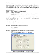
Example 1.
Make the following settings to the 81 element and to the inhibit function. See Figure 4-48.
Pickup Hertz:
59.5
Time:
2 ms
Mode:
Underfrequency
Voltage INHIBIT:
100 Vpn secondary volts
Retrieving Over/Underfrequency Status from the Relay
The status of each logic variable can be determined through the ASCII command interface using the RG-
STAT (report general-status) command. See Section 6,
Reporting and Alarm Functions, General Status
Reporting
, for more information. The status can also be determined using BESTCOMS
Metering
screen.
Summary of Contents for BE1-CDS240
Page 2: ......
Page 8: ...vi BE1 CDS240 Introduction 9365200990 Rev F This page intentionally left blank ...
Page 38: ...1 28 BE1 CDS240 General Information 9365200990 Rev F This page intentionally left blank ...
Page 40: ...ii BE1 CDS240 Quick Start 9365200990 Rev F This page intentionally left blank ...
Page 152: ...ii BE1 CDS240 Metering 9365200990 Rev F This page intentionally left blank ...
Page 226: ...iv BE1 CDS240 Application 9365200990 Rev F This page intentionally left blank ...
Page 286: ...ii BE1 CDS240 Security 9365200990 Rev F This page intentionally left blank ...
Page 290: ...9 4 BE1 CDS240 Security 9365200990 Rev F This page intentionally left blank ...
Page 292: ...ii BE1 CDS240 Human Machine Interface 9365200990 Rev F This page intentionally left blank ...
Page 306: ...10 14 BE1 CDS240 Human Machine Interface 9365200990 Rev F This page intentionally left blank ...
Page 308: ...ii BE1 CDS240 ASCII Command Interface 9365200990 Rev F This page intentionally left blank ...
Page 342: ...11 34 BE1 CDS240 ASCII Command Interface 9365200990 Rev F This page intentionally left blank ...
Page 349: ...Figure 12 5 Horizontal Rack Mount Front View 9365200990 Rev F BE1 CDS240 Installation 12 5 ...
Page 361: ...Figure 12 17 Typical DC Connection Diagrams 9365200990 Rev F BE1 CDS240 Installation 12 17 ...
Page 372: ...12 28 BE1 CDS240 Installation 9365200990 Rev F This page intentionally left blank ...
Page 468: ...13 92 BE1 CDS240 Testing and Maintenance 9365200990 Rev F This page intentionally left blank ...
Page 512: ...14 42 BE1 CDS240 BESTCOMS Software 9365200990 Rev F This page intentionally left blank ...
Page 544: ...ii BE1 CDS240 Terminal Communication 9365200990 Rev F This page intentionally left blank ...
Page 550: ...ii BE1 CDS240 Settings Calculations 9365200990 Rev F This page intentionally left blank ...
Page 578: ...D 28 BE1 CDS240 Settings Calculations 9365200990 Rev F This page intentionally left blank ...
Page 579: ......


