


9365200990 Rev F
BE1-CDS240 Quick Start
2-9
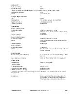
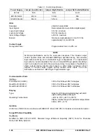
13.) Does the BE1-CDS240 have a battery installed as the back-up power source for the
internal clock on loss of power?
Yes, as an option. The relay also uses a capacitor as a back-up power source for the internal
clock on loss of power. This design maintains the clock for at least eight hours. See Section 1,
General Information,
Specifications
, for additional information.
14.) Since the BE1-CDS240 has overcurrent elements in addition to the differential protection
functions, are the timing curves the same as Basler Electric's other numeric overcurrent
relays?
Yes, the timing curves are the same as other Basler Electric numerical overcurrent relays such
as the BE1-851, BE1-951, and BE1-IPS100.
15.) Why do I keep getting access conflict errors when I am communicating with the relay?
If you have tried to gain access to more than one port at a time, an access conflict results. The
unit has three different communication ports. The front HMI and front RS-232 are considered
the same port and are the first port (COM 0). The rear RS-232 (COM 1) is the second and the
rear RS-485 (COM 2) is the third port. If you have gained access at the front panel HMI and the
5-minute timeout has not ended, you cannot gain access at another port. The front RS-232 can
still be accessed because the HMI and front RS-232 are considered the same port. Access
needs to be gained only when a write to the BE1-CDS240 is required (control or setting change
or report reset). Data can be read and reports can be obtained without gaining access. After
gaining access though one of the ports, the session can be ended with the Exit command. If
access is gained, but the session is not ended, a 5-minute timeout will end the session and any
changes that were not saved will be lost. If you are using the BESTCOMS program, the access
and exit commands are executed for you.
16.) Why doesn't the trip LED behave as expected when the relay picks up and trips? A
closely related question would be why don't the targets work?
If the logic is setup to the point were the protective element is tripping at the desired current
level, but the targets, trip LED, and fault records are not behaving as expected, then there are
two commands (SG-TRIGGER and SG-TARGET) that need to be checked for proper
operation. The SG-TRIGGER command needs to have the PU trigger and TRIP trigger logic
correctly programmed. This should initiate the fault record. The SG-TARGET command needs
the protective element (function) enabled to log targets. See Section 6,
Reporting and Alarm
Functions, Fault Reporting
, to get more details on how to correctly program these commands.
The trip LED has two different functions in the relay. When the SG-TRIGGER PU expression is
true and the TRIP expression is false, the trip LED flashes. When both the SG-TRIGGER PU
and TRIP expression are true, the trip LED lights solidly. When neither expression is true, the
trip LED lights solidly if there are latched targets. A flashing LED means one of the protection
elements is in a picked-up state and timing towards trip. Once the trip occurs, the LED turns on
solidly. The LED will not change state until the target has been reset. If the fault has not
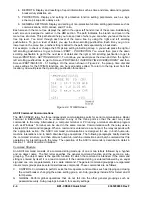
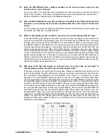
cleared, the LED turns on again. Table 2-2 is a truth table for the Trip LED and it should help to
interpret the LED indications.
Table 2-2. Trip LED Truth Table
Trip PU
Targets
LED
0 0 0 Off
0 0 1 On
0 1 0
Flash
0 1 1
Flash
1 0 0 On
1 0 1 On
1 1 0 On
1 1 1 On
Summary of Contents for BE1-CDS240
Page 2: ......
Page 8: ...vi BE1 CDS240 Introduction 9365200990 Rev F This page intentionally left blank ...
Page 38: ...1 28 BE1 CDS240 General Information 9365200990 Rev F This page intentionally left blank ...
Page 40: ...ii BE1 CDS240 Quick Start 9365200990 Rev F This page intentionally left blank ...
Page 152: ...ii BE1 CDS240 Metering 9365200990 Rev F This page intentionally left blank ...
Page 226: ...iv BE1 CDS240 Application 9365200990 Rev F This page intentionally left blank ...
Page 286: ...ii BE1 CDS240 Security 9365200990 Rev F This page intentionally left blank ...
Page 290: ...9 4 BE1 CDS240 Security 9365200990 Rev F This page intentionally left blank ...
Page 292: ...ii BE1 CDS240 Human Machine Interface 9365200990 Rev F This page intentionally left blank ...
Page 306: ...10 14 BE1 CDS240 Human Machine Interface 9365200990 Rev F This page intentionally left blank ...
Page 308: ...ii BE1 CDS240 ASCII Command Interface 9365200990 Rev F This page intentionally left blank ...
Page 342: ...11 34 BE1 CDS240 ASCII Command Interface 9365200990 Rev F This page intentionally left blank ...
Page 349: ...Figure 12 5 Horizontal Rack Mount Front View 9365200990 Rev F BE1 CDS240 Installation 12 5 ...
Page 361: ...Figure 12 17 Typical DC Connection Diagrams 9365200990 Rev F BE1 CDS240 Installation 12 17 ...
Page 372: ...12 28 BE1 CDS240 Installation 9365200990 Rev F This page intentionally left blank ...
Page 468: ...13 92 BE1 CDS240 Testing and Maintenance 9365200990 Rev F This page intentionally left blank ...
Page 512: ...14 42 BE1 CDS240 BESTCOMS Software 9365200990 Rev F This page intentionally left blank ...
Page 544: ...ii BE1 CDS240 Terminal Communication 9365200990 Rev F This page intentionally left blank ...
Page 550: ...ii BE1 CDS240 Settings Calculations 9365200990 Rev F This page intentionally left blank ...
Page 578: ...D 28 BE1 CDS240 Settings Calculations 9365200990 Rev F This page intentionally left blank ...
Page 579: ......


