


BREAKER FAILURE PROTECTION
50BF - Breaker Failure Protection
BE1-CDS240 relays provide four independent breaker failure protection functions. Each current circuit
has an associated breaker failure function. For example, Current Circuit 1 is internally connected to 50BF;
Current Circuit 2 is internally connected to 150 BF and so on. This section discuses 50BF but applies to
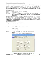
all BF functions. Figure 4-49 shows the breaker failure function block which has two outputs,
BFRT (1, 2,
3, 4)
(Breaker Failure Retrip) and BFT
(1, 2, 3, 4)
(Breaker Failure trip) which is true after the breaker
failure
Delay Timer
has timed out. The
BFIALM
(1, 2, 3, 4) (Breaker failure initiate alarm) occurs if the
Control Timer
has expired (closing the window of breaker failure opportunity), and there is no
BLK
(Block
input) and the BFI50 (internal protection element) is still calling for a trip.
Figure 4-49. Breaker Failure Logic Block
A BESTlogic expression defines how the
BLK
(Block) input functions. When this expression is TRUE, the
element is disabled by forcing the outputs to logic 0 and resetting the timer to zero. For example, this may
be an input wired to a test switch such that breaker failure protection is disabled when the primary
protective elements are being tested to prevent inadvertent backup tripping during testing.
The breaker failure
Delay Timer
is stopped by the fast-dropout current detector function. See Section 3,
Input and Output Functions, Power System Inputs, Current Measurement,
for more details on this
function. The fast-dropout current detector is designed to directly determine when the current in the poles
of the breaker has been interrupted without having to wait for the fault current samples to clear the one-
cycle filter time used by the normal current measurement function. This function has less than one cycle
dropout time. The
Delay Timer
can also be stopped by the
BLK
(Block) logic input being asserted.
Upon sensing
50 INI
transition from 0 to 1 state, a
Control Timer
seals in the
50 INI
signal for the duration
of the
Control Timer
setting. If the
Control Timer
expires and the
50 INI
signal is still present, a
BFIALM
(Breaker Failure Initiate Alarm) signal will occur. The
Control Timer
serves the purpose to improve
security by presenting a window of opportunity for the breaker failure element to operate. It improves
dependability by sealing in the initiate to prevent stopping breaker failure timing if the tripping relay drops
out prematurely. A
Control Timer
setting of zero shall disable the control timer seal in function allowing
the
Control Timer
to follow the
50 INI
input.
Phase and neutral fault detectors are provided to monitor current. At least one of these four fault
detectors must be picked up to start the breaker failure
Delay Timer
.
The current detector logic is TRUE if the current has been interrupted and is used to stop the BF timer.
The I = 0 algorithm looks at the sample data directly and does not rely upon the 1 cycle phasor estimation
calculation. It rejects dc tail-off by looking for the characteristic exponential decay. Current shall be
declared interrupted when the current in all three phases is below 10% nominal or if the current is
decaying exponentially. Only the three phase currents shall be monitored by this function.
Logic to start the breaker failure timing via the
52 INI
input is provided with breaker status supervision.
Both the
52 STATUS
and the
52 INI
have to be TRUE for a
52 INI
to cause a trip condition. A breaker
status logic input monitors the breaker state.
The breaker failure timer is initiated by the either the
52 INI
or the
50 INI
. When both signals are in the
zero state the breaker failure
Delay Timer
will be stopped. When the breaker failure
Delay Timer
is
actively timing, the
BFRT
(Breaker Failure Retrip) output shall be TRUE. When the breaker failure
Delay
9365200990 Rev F
BE1-CDS240 Protection and Control
4-55
Summary of Contents for BE1-CDS240
Page 2: ......
Page 8: ...vi BE1 CDS240 Introduction 9365200990 Rev F This page intentionally left blank ...
Page 38: ...1 28 BE1 CDS240 General Information 9365200990 Rev F This page intentionally left blank ...
Page 40: ...ii BE1 CDS240 Quick Start 9365200990 Rev F This page intentionally left blank ...
Page 152: ...ii BE1 CDS240 Metering 9365200990 Rev F This page intentionally left blank ...
Page 226: ...iv BE1 CDS240 Application 9365200990 Rev F This page intentionally left blank ...
Page 286: ...ii BE1 CDS240 Security 9365200990 Rev F This page intentionally left blank ...
Page 290: ...9 4 BE1 CDS240 Security 9365200990 Rev F This page intentionally left blank ...
Page 292: ...ii BE1 CDS240 Human Machine Interface 9365200990 Rev F This page intentionally left blank ...
Page 306: ...10 14 BE1 CDS240 Human Machine Interface 9365200990 Rev F This page intentionally left blank ...
Page 308: ...ii BE1 CDS240 ASCII Command Interface 9365200990 Rev F This page intentionally left blank ...
Page 342: ...11 34 BE1 CDS240 ASCII Command Interface 9365200990 Rev F This page intentionally left blank ...
Page 349: ...Figure 12 5 Horizontal Rack Mount Front View 9365200990 Rev F BE1 CDS240 Installation 12 5 ...
Page 361: ...Figure 12 17 Typical DC Connection Diagrams 9365200990 Rev F BE1 CDS240 Installation 12 17 ...
Page 372: ...12 28 BE1 CDS240 Installation 9365200990 Rev F This page intentionally left blank ...
Page 468: ...13 92 BE1 CDS240 Testing and Maintenance 9365200990 Rev F This page intentionally left blank ...
Page 512: ...14 42 BE1 CDS240 BESTCOMS Software 9365200990 Rev F This page intentionally left blank ...
Page 544: ...ii BE1 CDS240 Terminal Communication 9365200990 Rev F This page intentionally left blank ...
Page 550: ...ii BE1 CDS240 Settings Calculations 9365200990 Rev F This page intentionally left blank ...
Page 578: ...D 28 BE1 CDS240 Settings Calculations 9365200990 Rev F This page intentionally left blank ...
Page 579: ......


