


9365200990 Rev F
BE1-CDS240 Testing and Maintenance
13-71
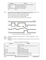
Step 5:
Slowly decrease the frequency of the applied voltage until OUT3 (281) closes. Pickup should
occur 0.01 hertz of the pickup setting. Slowly increase the frequency until OUT3
opens. Dropout should occur at 0.02 hertz above or below the pickup setting.
Step 6:
Repeat Step 5 for the 181 (OUT2) and 81 (OUT1) functions.
Step 7:
Repeat Step 4.
Step 8:
Slowly increase the frequency of the applied voltage until OUT4 (381) closes. Pickup should
occur 0.01 hertz of the pickup setting. Slowly decrease the frequency until OUT4
opens. Dropout should occur at 0.02 hertz above or below the pickup setting.
Step 9:
Repeat Step 5 for the 481 (OUT5) and 581 (OUT1) functions.
Step 10: Repeat Steps 5 through 9.
Step 11: (Optional.) Repeat Steps 1 through 11 for Setting Groups 1, 2, and 3.
Time Delay Verification
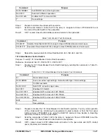
Step 1:
Prepare the x81 functions for time delay testing by transmitting the commands in the first
column (2 second TD) of Table 13-75 to the relay. Commands entered in Tables 13-73 and
13-74 should be retained for this test.
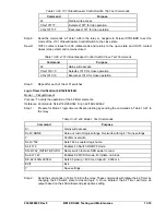
Table 13-75. x81 Time Delay Settings
Pickup and Time Delay Settings
2 Second TD
5 Second TD
10 Second TD
Purpose
S0-81=,2S S0-81=,5S S0-81=,10S
Sets 81 TD
S0-181=,2S
S0-181=,5S
S0-181=,10S
Sets 181 TD
S0-281=,2S
S0-281=,5S
S0-281=,10S
Sets 281 TD
S0-381=,2S
S0-381=,5S
S0-381=,10S
Sets 381 TD
S0-481=,2S
S0-481=,5S
S0-481=,10S
Sets 481 TD
S0-581=,2S
S0-581=,5S
S0-581=,10S
Sets 581 TD
Step 2:
Prepare to monitor the x81 timings. Timing accuracy is verified by measuring the elapsed time
between a frequency change and programmed output closing.
Step 3:
Connect and apply a 120 Vac, 60-hertz voltage source to terminals B9 (A-phase) and B12
(Neutral).
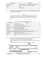
Step 4:
Step the frequency of the applied voltage down from 60 hertz to a value below the 281
underfrequency setting. Measure the time delay and verify the accuracy of the 281 time delay
setting. Timing accuracy is +5 percent or +3 cycles of the time delay setting.
Step 5:
Repeat Step 4 for the 181 (OUT2) and 81 (OUT1) elements.
Step 6:
Step the frequency of the applied voltage up from 60 hertz to a value above the 381
overfrequency setting. Measure the time delay and verify the accuracy of the 281 time delay
setting. Timing accuracy is +5 percent or +3 cycles of the time delay setting.
Step 7:
Repeat Step 6 for the 481 (OUT5) and 581 (OUT1) elements.
Step 8:
Transmit the commands in the second column (5 Second TD) of Table 13-75 to the relay.
Step 9:
Repeat Steps 2 through 7 with a time delay setting of 5 seconds.
Step 10: Transmit the commands in the third column (10 Second TD) of Table 13-75 to the relay.
Step 11: Repeat Steps 2 through 7 with a time delay setting of 10 seconds.
Step 12: (Optional.) Repeat Steps 1 through 11 for Setting Groups 1, 2, and 3.
Breaker Failure (50BF/150BF/250BF/350BF)
Purpose:
To verify the operation of the breaker failure (BF) elements.
Reference Commands:
SL-x50BF, S<x>-x50BF
The CDS240 has two types of Breaker Failure Initiate, one being contact only, and the other being current
supervised relay trip initiate. The following tests are for
Contact Only Initiate
.
Summary of Contents for BE1-CDS240
Page 2: ......
Page 8: ...vi BE1 CDS240 Introduction 9365200990 Rev F This page intentionally left blank ...
Page 38: ...1 28 BE1 CDS240 General Information 9365200990 Rev F This page intentionally left blank ...
Page 40: ...ii BE1 CDS240 Quick Start 9365200990 Rev F This page intentionally left blank ...
Page 152: ...ii BE1 CDS240 Metering 9365200990 Rev F This page intentionally left blank ...
Page 226: ...iv BE1 CDS240 Application 9365200990 Rev F This page intentionally left blank ...
Page 286: ...ii BE1 CDS240 Security 9365200990 Rev F This page intentionally left blank ...
Page 290: ...9 4 BE1 CDS240 Security 9365200990 Rev F This page intentionally left blank ...
Page 292: ...ii BE1 CDS240 Human Machine Interface 9365200990 Rev F This page intentionally left blank ...
Page 306: ...10 14 BE1 CDS240 Human Machine Interface 9365200990 Rev F This page intentionally left blank ...
Page 308: ...ii BE1 CDS240 ASCII Command Interface 9365200990 Rev F This page intentionally left blank ...
Page 342: ...11 34 BE1 CDS240 ASCII Command Interface 9365200990 Rev F This page intentionally left blank ...
Page 349: ...Figure 12 5 Horizontal Rack Mount Front View 9365200990 Rev F BE1 CDS240 Installation 12 5 ...
Page 361: ...Figure 12 17 Typical DC Connection Diagrams 9365200990 Rev F BE1 CDS240 Installation 12 17 ...
Page 372: ...12 28 BE1 CDS240 Installation 9365200990 Rev F This page intentionally left blank ...
Page 468: ...13 92 BE1 CDS240 Testing and Maintenance 9365200990 Rev F This page intentionally left blank ...
Page 512: ...14 42 BE1 CDS240 BESTCOMS Software 9365200990 Rev F This page intentionally left blank ...
Page 544: ...ii BE1 CDS240 Terminal Communication 9365200990 Rev F This page intentionally left blank ...
Page 550: ...ii BE1 CDS240 Settings Calculations 9365200990 Rev F This page intentionally left blank ...
Page 578: ...D 28 BE1 CDS240 Settings Calculations 9365200990 Rev F This page intentionally left blank ...
Page 579: ......


