


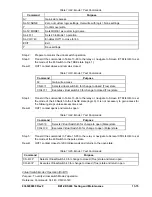


Command
Purpose
SL-62=6,43,143
Enables 62 latch mode, 43 initiate, 143 block (reset latch).
S0-62=30s
Sets T1 at 30 seconds, T2 time not applicable.
EXIT
Exit.
Y Save
settings.
Step 2:
Sent the commands in Table 13-107 to the relay. These commands supply a latch input to the
62 Timer by changing the 43 Switch state to TRUE and a reset command by changing the
BLK input (143 Switch) to TRUE.
NOTE
The CS and CO commands of Table 13-104 are performed two times. Follow the
timing sequence to illustrate timer mode action. The time delay settings may be
increased if difficulty is encountered with repeating the 43 and 143 Switch
actions.
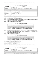
Table 13-107. x62 Mode 6 Timer Initiate Commands
Command
Purpose
A=
Gains write access.
CS-43=P
Selects 43 for pulse operation.
CO-43=P
Executes 43 for pulse operation (initiates 62 timing).
Execute the following commands in less than 30 seconds.
CS-43=P
Selects 43 for pulse operation.
CO-43=P
Executes 43 for pulse operation (no effect).
Wait at least 30 seconds (total elapsed time) to initiate the latch reset (block) command (this allows
timer T1 to time out (output goes TRUE) and latch until the BLK input goes TRUE).
CS-143=P
Selects 143 for pulse operation.
CO-143=P
Executes 143 for pulse operation (applies BLK input).
E
Exit.
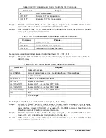
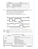
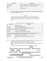
Step 3:
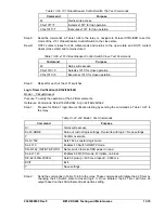
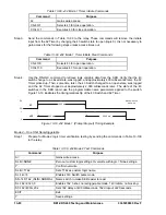
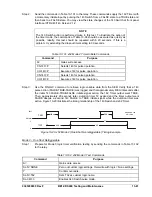
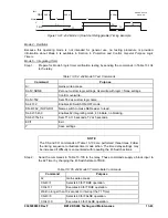
Use the RS-LGC command to obtain an SER report and verify that the following actions were
logged. These events are illustrated in the timing diagram of Figure 13-23.
Timer T1 continued to time out after the first 43 Switch action (TRUE).
Timer T1 timed out and the 62 Timer output went TRUE 30 seconds after 43 Switch action
(TRUE).
62 Timer output returned to a FALSE state with the 143 Switch action (TRUE).
200 ms
200 ms
T1
INI
x62
1
1
0
0
D2595-06.vsd
08-10-00
BLK
1
0
~ ~
Figure 13-23. x62 Mode 6 (Latch) Timing Example
9365200990 Rev F
BE1-CDS240 Testing and Maintenance
13-85
Summary of Contents for BE1-CDS240
Page 2: ......
Page 8: ...vi BE1 CDS240 Introduction 9365200990 Rev F This page intentionally left blank ...
Page 38: ...1 28 BE1 CDS240 General Information 9365200990 Rev F This page intentionally left blank ...
Page 40: ...ii BE1 CDS240 Quick Start 9365200990 Rev F This page intentionally left blank ...
Page 152: ...ii BE1 CDS240 Metering 9365200990 Rev F This page intentionally left blank ...
Page 226: ...iv BE1 CDS240 Application 9365200990 Rev F This page intentionally left blank ...
Page 286: ...ii BE1 CDS240 Security 9365200990 Rev F This page intentionally left blank ...
Page 290: ...9 4 BE1 CDS240 Security 9365200990 Rev F This page intentionally left blank ...
Page 292: ...ii BE1 CDS240 Human Machine Interface 9365200990 Rev F This page intentionally left blank ...
Page 306: ...10 14 BE1 CDS240 Human Machine Interface 9365200990 Rev F This page intentionally left blank ...
Page 308: ...ii BE1 CDS240 ASCII Command Interface 9365200990 Rev F This page intentionally left blank ...
Page 342: ...11 34 BE1 CDS240 ASCII Command Interface 9365200990 Rev F This page intentionally left blank ...
Page 349: ...Figure 12 5 Horizontal Rack Mount Front View 9365200990 Rev F BE1 CDS240 Installation 12 5 ...
Page 361: ...Figure 12 17 Typical DC Connection Diagrams 9365200990 Rev F BE1 CDS240 Installation 12 17 ...
Page 372: ...12 28 BE1 CDS240 Installation 9365200990 Rev F This page intentionally left blank ...
Page 468: ...13 92 BE1 CDS240 Testing and Maintenance 9365200990 Rev F This page intentionally left blank ...
Page 512: ...14 42 BE1 CDS240 BESTCOMS Software 9365200990 Rev F This page intentionally left blank ...
Page 544: ...ii BE1 CDS240 Terminal Communication 9365200990 Rev F This page intentionally left blank ...
Page 550: ...ii BE1 CDS240 Settings Calculations 9365200990 Rev F This page intentionally left blank ...
Page 578: ...D 28 BE1 CDS240 Settings Calculations 9365200990 Rev F This page intentionally left blank ...
Page 579: ......


