


9365200990 Rev F
BE1-CDS240 Application
8-9
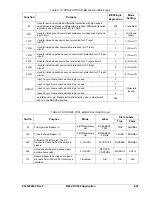
Output Purpose
Description
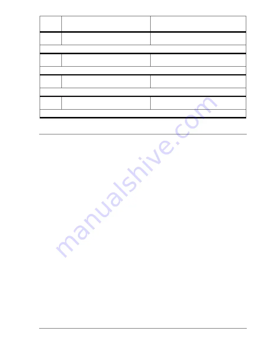
OUT4
Time overcurrent trip. May be used to direct trip
main breaker or lockout.
OUT4 contact closes if any time overcurrent (51N,
151P, N, or Q) trip occurs.
BESTlogic Expression: OUT4=VO4
OUT5
Time overcurrent trip. May be used to direct trip
main breaker or lockout.
OUT5 contact closes if any time overcurrent (251P,
N, or Q) trip occurs.
BESTlogic Expression: OUT5=VO5
OUT6
Used to annunciate an alarm.
OUT6 contact closes when any programmed major
alarm condition is TRUE.
BESTlogic Expression: OUT6=VO6
OUT7 -
14
Spare output contacts.
N/A
BESTlogic Expression: OUT7-14 =0
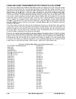
OVERVIEW OF ADDITIONAL PREPROGRAMMED LOGIC SCHEMES
The following preprogrammed logic schemes can be found in logic library of BESTCOMS for the CDS240
or at the Basler Electric Web site. Two of the logic schemes are intended for use on transformers. One of
the schemes is for motor protection with a speed sensing input, one is for bus protection with backup, and
one is a basic 87 function designed for multiple applications including transformer, motor, bus, or
generator protection.
The 87 function as applied to transformer protection is fundamentally different from the application of the
87 function to motors, generators, and buses. That is, the 2
nd
and 5
th
harmonic restraint elements are
required on transformer applications to prevent false tripping resulting from magnetizing inrush currents.
However, waveform distortion resulting from heavy current transformer (CT) saturation can cause the
harmonic restraint units to block restrained differential tripping (87RT) for internal faults. Therefore, a
high-speed, unrestrained instantaneous differential element (87UT) is also required for transformer
applications.
When the 87 protection element is applied to other than transformer protection, set the pickup thresholds
for the 2
nd
, 5
th
, and 87UT units to 0 (setting disabled).
CDS240-BA87-B-BE (Basic Differential) Logic Scheme
This logic scheme (CDS240-BA87-B-BE) provides three-phase, percent-restrained differential protection,
with high-speed unrestrained instantaneous differential protection for motor, generator, bus, and
transformer applications. A single zone of time overcurrent phase, neutral and negative sequence
protection (51P, N, and Q) is also included for backup protection.
CDS240-TXCL-B-BE (Basic Transformer with Control) Logic Scheme
This logic scheme (CDS240-TXCL-B-BE) provides the same differential and overcurrent protection
elements as the basic transformer logic scheme but with different outputs and the addition of virtual
control switch logic that can be operated locally or remotely (SCADA). The Virtual 101 Control Switch is
applied for tripping and closing the low-side breaker, while 43 and 143 Control Switch elements are
applied for tripping and closing the high-side breaker. Virtual Control Switch 243 is used to turn off the
differential protection element and Virtual Control Switch 343 allows for automatic or manual selection of
the active setting group.
CDS240-TXBU-B-BE (Transformer Differential with Backup) Logic Scheme
This logic (CDS240-TXBU-B-BE) incorporates nearly all the protection elements available in the BE1-
CDS240. These include the differential functions with harmonic restraint as well as 51 phase, neutral, and
negative-sequence backup protection as seen from the transformer high side. Also included is a separate
Summary of Contents for BE1-CDS240
Page 2: ......
Page 8: ...vi BE1 CDS240 Introduction 9365200990 Rev F This page intentionally left blank ...
Page 38: ...1 28 BE1 CDS240 General Information 9365200990 Rev F This page intentionally left blank ...
Page 40: ...ii BE1 CDS240 Quick Start 9365200990 Rev F This page intentionally left blank ...
Page 152: ...ii BE1 CDS240 Metering 9365200990 Rev F This page intentionally left blank ...
Page 226: ...iv BE1 CDS240 Application 9365200990 Rev F This page intentionally left blank ...
Page 286: ...ii BE1 CDS240 Security 9365200990 Rev F This page intentionally left blank ...
Page 290: ...9 4 BE1 CDS240 Security 9365200990 Rev F This page intentionally left blank ...
Page 292: ...ii BE1 CDS240 Human Machine Interface 9365200990 Rev F This page intentionally left blank ...
Page 306: ...10 14 BE1 CDS240 Human Machine Interface 9365200990 Rev F This page intentionally left blank ...
Page 308: ...ii BE1 CDS240 ASCII Command Interface 9365200990 Rev F This page intentionally left blank ...
Page 342: ...11 34 BE1 CDS240 ASCII Command Interface 9365200990 Rev F This page intentionally left blank ...
Page 349: ...Figure 12 5 Horizontal Rack Mount Front View 9365200990 Rev F BE1 CDS240 Installation 12 5 ...
Page 361: ...Figure 12 17 Typical DC Connection Diagrams 9365200990 Rev F BE1 CDS240 Installation 12 17 ...
Page 372: ...12 28 BE1 CDS240 Installation 9365200990 Rev F This page intentionally left blank ...
Page 468: ...13 92 BE1 CDS240 Testing and Maintenance 9365200990 Rev F This page intentionally left blank ...
Page 512: ...14 42 BE1 CDS240 BESTCOMS Software 9365200990 Rev F This page intentionally left blank ...
Page 544: ...ii BE1 CDS240 Terminal Communication 9365200990 Rev F This page intentionally left blank ...
Page 550: ...ii BE1 CDS240 Settings Calculations 9365200990 Rev F This page intentionally left blank ...
Page 578: ...D 28 BE1 CDS240 Settings Calculations 9365200990 Rev F This page intentionally left blank ...
Page 579: ......


