


100 volts, M-VCA = 100 volts, M-3V0 = 100 volts and M-V2 = 33.4 volts (applied divided by 3),
all at +1.0%. HMI Screens 3.1.1, 3.1.2 and 3.1.3 can also be monitored to verify voltage
measurements.
Step 2:
Connect an ac voltage source at nominal frequency between relay terminals B10 (B-phase)
and B12 (Neutral terminal). Apply 100 volts and verify voltage-measuring accuracy by
transmitting the M command to the relay. Readings should be: M-VB = 100 volts, M-VAB =
100 volts, M-VBC = 100 volts, M-3V0 = 100 volts and M-V2 = 33.4 volts (applied divided by 3),
all at +1.0%. HMI Screens 3.1.1, 3.1.2 and 3.1.3 can also be monitored to verify voltage
measurements.
Step 3:
Connect an ac voltage source at nominal frequency between relay Terminals B11 (C-phase)
and B12 (Neutral terminal). Apply 100 volts and verify voltage-measuring accuracy by
transmitting the M command to the relay. Readings should be: M-VC = 100 volts, M-VBC =
100 volts, M-VCA = 100 volts, M-3V0 = 100 volts and M-V2 = 33.4 volts (applied divided by 3),
all at +1.0%. HMI Screens 3.1.1, 3.1.2 and 3.1.3 can also be monitored to verify voltage
measurements.
Step 4:
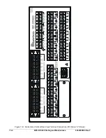
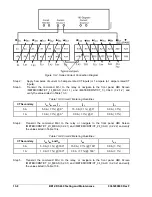
Connect relay terminals B9 (A-phase), B10 (B-phase) and B11 (C-phase) together. Connect
an ac voltage source at nominal frequency to the three jumpered terminals and the Neutral
terminal (B12).
Step 5:
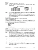
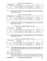
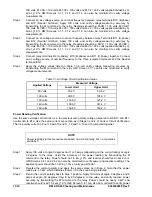
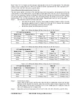
Apply the voltage values listed in Table 13-9 and verify voltage measuring accuracy by
transmitting the M command to the relay. HMI Screen 3.1.1 can also be monitored to verify
voltage measurements.
Table 13-9. Voltage Circuit Verification Values
Measured Voltage
Applied Voltage
Lower Limit
Upper Limit
80 volts
79.2 V
80.8 V
100 volts
99.0 V
101.0 V
120 volts
118.8 V
121.2 V
140 volts
138.6 V
141.4 V
160 volts
156.8 V
163.2 V
Power Reading Verification
Use the same voltage connections as in the previous test, polarity voltage jumpered to B9, B10 and B11,
neutral tied to B12. Use the same current connection as in Steps 3 and 4 of Current Circuit Verification.
That is, polarity current in 9 out 16 with 10 and 11, 12 and 13, 14 and 15 jumpered together.
NOTE
Power readings in this procedure are based on a 5-amp relay. For 1-amp values,
divide by 5.
Step 1:
Apply 100 volts at angle 0 degrees and 1 or 5 amps (depending on the current rating) at angle
0 degrees to the relay. Verify the accuracy of the power reading by transmitting the M
command to the relay. Power should be 1.5 kw +1.0% and reactive should read near 0 vars.
HMI Screens 3.4.1 and 3.4.2 can also be monitored to verify power and reactive readings. The
apparent power should be 1.5 kVA +1.0% at unity power factor.
Step 2:
Reverse the current polarity and apply the same values as in Step 2. Note that the power
reading is -1.5 kW, which indicates "power in" to the zone being protected.
13-10
BE1-CDS240 Testing and Maintenance
9365200990 Rev F
Step 3:
Return the current polarity back to Step 1 position. Apply 100 volts at angle 0 degrees, and 5
amps at angle -90 degrees (I lag E by 90 degrees) to the relay, and verify reactive power
accuracy by transmitting the M command to the relay. Power should be nearly 0 kW, and
reactive should read 1.5 kvar +1.0%. HMI Screen 3.4.1 can also be monitored to verify power
Summary of Contents for BE1-CDS240
Page 2: ......
Page 8: ...vi BE1 CDS240 Introduction 9365200990 Rev F This page intentionally left blank ...
Page 38: ...1 28 BE1 CDS240 General Information 9365200990 Rev F This page intentionally left blank ...
Page 40: ...ii BE1 CDS240 Quick Start 9365200990 Rev F This page intentionally left blank ...
Page 152: ...ii BE1 CDS240 Metering 9365200990 Rev F This page intentionally left blank ...
Page 226: ...iv BE1 CDS240 Application 9365200990 Rev F This page intentionally left blank ...
Page 286: ...ii BE1 CDS240 Security 9365200990 Rev F This page intentionally left blank ...
Page 290: ...9 4 BE1 CDS240 Security 9365200990 Rev F This page intentionally left blank ...
Page 292: ...ii BE1 CDS240 Human Machine Interface 9365200990 Rev F This page intentionally left blank ...
Page 306: ...10 14 BE1 CDS240 Human Machine Interface 9365200990 Rev F This page intentionally left blank ...
Page 308: ...ii BE1 CDS240 ASCII Command Interface 9365200990 Rev F This page intentionally left blank ...
Page 342: ...11 34 BE1 CDS240 ASCII Command Interface 9365200990 Rev F This page intentionally left blank ...
Page 349: ...Figure 12 5 Horizontal Rack Mount Front View 9365200990 Rev F BE1 CDS240 Installation 12 5 ...
Page 361: ...Figure 12 17 Typical DC Connection Diagrams 9365200990 Rev F BE1 CDS240 Installation 12 17 ...
Page 372: ...12 28 BE1 CDS240 Installation 9365200990 Rev F This page intentionally left blank ...
Page 468: ...13 92 BE1 CDS240 Testing and Maintenance 9365200990 Rev F This page intentionally left blank ...
Page 512: ...14 42 BE1 CDS240 BESTCOMS Software 9365200990 Rev F This page intentionally left blank ...
Page 544: ...ii BE1 CDS240 Terminal Communication 9365200990 Rev F This page intentionally left blank ...
Page 550: ...ii BE1 CDS240 Settings Calculations 9365200990 Rev F This page intentionally left blank ...
Page 578: ...D 28 BE1 CDS240 Settings Calculations 9365200990 Rev F This page intentionally left blank ...
Page 579: ......


