


scheme must be created and selected in the
Logic
pull-down menu at the top of the screen before
BESTlogic settings can be changed. See Section 7,
BESTlogic Programmable Logic
.
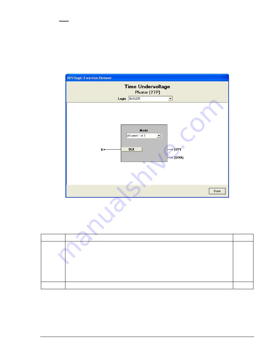
Enable the element by selecting its mode of operation from the
Mode
pull-down menu. To connect the
elements inputs, select the button for the corresponding input in the
BESTlogic Function Element
screen.
The
BESTlogic Expression Builder
screen will open. Select the expression type to be used. Then, select
the BESTlogic variable, or series of variables to be connected to the input. Select
Save
when finished to
return to the
BESTlogic Function Element
screen. For more details on the
BESTlogic Expression Builder
,
see Section 7,
BESTlogic Programmable Logic
. Select
Done
when the settings have been completely
edited.
Figure 4-38. BESTlogic Function Element Screen, Phase (27P)
Table 4-22 summarizes the BESTlogic settings for Phase Undervoltage/Overvoltage.
Table 4-22. BESTlogic settings for Phase Undervoltage/Overvoltage
Function Range/Purpose Default
0 = Disabled
1 =
Undervoltage (27) or overvoltage (59) on one (or more) phases causes
pickup.
2 =
Undervoltage (27) or overvoltage (59) on two (or more) phases causes
pickup.
Mode
3 = Undervoltage or overvoltage on all three phases causes pickup.
0
BLK
Logic expression that disables function when TRUE.
0
Example 1.
Make the following BESTlogic settings to the 27P element. Refer to Figure 4-38.
Mode:
At least 1of 3 phases
BLK:
0
9365200990 Rev F
BE1-CDS240 Protection and Control
4-43
Summary of Contents for BE1-CDS240
Page 2: ......
Page 8: ...vi BE1 CDS240 Introduction 9365200990 Rev F This page intentionally left blank ...
Page 38: ...1 28 BE1 CDS240 General Information 9365200990 Rev F This page intentionally left blank ...
Page 40: ...ii BE1 CDS240 Quick Start 9365200990 Rev F This page intentionally left blank ...
Page 152: ...ii BE1 CDS240 Metering 9365200990 Rev F This page intentionally left blank ...
Page 226: ...iv BE1 CDS240 Application 9365200990 Rev F This page intentionally left blank ...
Page 286: ...ii BE1 CDS240 Security 9365200990 Rev F This page intentionally left blank ...
Page 290: ...9 4 BE1 CDS240 Security 9365200990 Rev F This page intentionally left blank ...
Page 292: ...ii BE1 CDS240 Human Machine Interface 9365200990 Rev F This page intentionally left blank ...
Page 306: ...10 14 BE1 CDS240 Human Machine Interface 9365200990 Rev F This page intentionally left blank ...
Page 308: ...ii BE1 CDS240 ASCII Command Interface 9365200990 Rev F This page intentionally left blank ...
Page 342: ...11 34 BE1 CDS240 ASCII Command Interface 9365200990 Rev F This page intentionally left blank ...
Page 349: ...Figure 12 5 Horizontal Rack Mount Front View 9365200990 Rev F BE1 CDS240 Installation 12 5 ...
Page 361: ...Figure 12 17 Typical DC Connection Diagrams 9365200990 Rev F BE1 CDS240 Installation 12 17 ...
Page 372: ...12 28 BE1 CDS240 Installation 9365200990 Rev F This page intentionally left blank ...
Page 468: ...13 92 BE1 CDS240 Testing and Maintenance 9365200990 Rev F This page intentionally left blank ...
Page 512: ...14 42 BE1 CDS240 BESTCOMS Software 9365200990 Rev F This page intentionally left blank ...
Page 544: ...ii BE1 CDS240 Terminal Communication 9365200990 Rev F This page intentionally left blank ...
Page 550: ...ii BE1 CDS240 Settings Calculations 9365200990 Rev F This page intentionally left blank ...
Page 578: ...D 28 BE1 CDS240 Settings Calculations 9365200990 Rev F This page intentionally left blank ...
Page 579: ......


