


13-2
BE1-CDS240 Testing and Maintenance
9365200990 Rev F
It is not the intent of this manual to elaborate on every conceivable test possible since this would
encroach on individual preferences, techniques, and philosophies. It is the intent to pursue relevant
testing methods to verify this relay meets published design specifications and applicability.
Functional Testing
Functional (or application) testing
is significantly more comprehensive in nature and is intended to test
suitability for a particular application. Functional testing also provides a means to familiarize the user with
the logic and operation of this device. Test setups are generally more involved and often times include
ancillary equipment beyond voltage or current source type equipment. While economics may at times
prohibit full functional testing, it is recommended that some application testing be performed when
published specifications lack appropriate detail to satisfy application-testing requirements.
Basler Electric performs a thorough and comprehensive functional test of all relays before shipping. This
ensures that this device is within specified tolerances, measures accurately, and operates correctly as
designed.
Performance Testing
Performance testing can be accomplished through the capture and playback of system fault records. In
actual applications, this type of test realizes further confirmation of faithful relay responses during system
disturbances. For specific power system disturbances, relays can be subjected to a recreation of captured
events with the aide of equipment capable of replicating COMTRADE record files. In these instances,
there is significant merit in testing relays in this manner to assess relay performance. Correct response of
relay action in a performance test is supplemental verification of the conclusions drawn from functional (or
application) tests.
This type of testing verifies not only whether or not the device operated correctly for a particular system
disturbance but also offers additional confirmation of your protection philosophy in this application. It is
beyond the scope of this manual to develop performance tests for this device. For assistance in
developing these types of tests, please consult Basler Electric and your test equipment manufacturer.
TESTING AND TROUBLESHOOTING AIDS
Under test or in-service, the BE1-CDS240 provides several ways to check operations, targets or events.
A continuous self-test monitors the system health and status. The most basic reporting function is targets.
Targets may be viewed through ASCII command interface or through the front panel human-machine
interface (HMI). Fault Summary Reports, Sequence of Events Recorder (SER) Reports, and
Oscillographic Records yield more detail.
Each time a system disturbance occurs in or around this relay’s zone of protection, it is a test of the relay
performance during the fault. If a questionable operation (or lack of) results in the need for
troubleshooting, you have several ways in which to troubleshoot the relay, the installation, and the overall
application.
Relay Self-Test
All internal circuitry and software that affect the relay core functionality are monitored by the continuous
self-test diagnostics. For specific relay trouble alarms, the self-test diagnostics force the microprocessor
to reset and try to correct the problem. If unsuccessful, OUTA operates, the Relay Trouble LED on the
front panel turns ON, all of the output relays are disabled, internal logic Point ALMREL is set, and the
relay is taken off line. For more information on self-test diagnostics and relay trouble alarms, see Section
6,
Reporting and Alarm Functions, Alarms Function.
Status and Event Reporting Features
General status reporting is available through the ASCII command interface using the RG-STAT (report
general, status) command or the front panel HMI with LCD display. This report assembles all of the
information required to determine the relay status. For more information on general status reporting, see
Section 6,
Reporting and Alarm Functions, General Status Reporting, General Status Report.
Several
different HMI screens display the same information. Section 6,
Reporting and Alarm Functions, General
Status Reporting, General Status Report,
details the location and number of each of the HMI screens for
every line in the general status report
.
Summary of Contents for BE1-CDS240
Page 2: ......
Page 8: ...vi BE1 CDS240 Introduction 9365200990 Rev F This page intentionally left blank ...
Page 38: ...1 28 BE1 CDS240 General Information 9365200990 Rev F This page intentionally left blank ...
Page 40: ...ii BE1 CDS240 Quick Start 9365200990 Rev F This page intentionally left blank ...
Page 152: ...ii BE1 CDS240 Metering 9365200990 Rev F This page intentionally left blank ...
Page 226: ...iv BE1 CDS240 Application 9365200990 Rev F This page intentionally left blank ...
Page 286: ...ii BE1 CDS240 Security 9365200990 Rev F This page intentionally left blank ...
Page 290: ...9 4 BE1 CDS240 Security 9365200990 Rev F This page intentionally left blank ...
Page 292: ...ii BE1 CDS240 Human Machine Interface 9365200990 Rev F This page intentionally left blank ...
Page 306: ...10 14 BE1 CDS240 Human Machine Interface 9365200990 Rev F This page intentionally left blank ...
Page 308: ...ii BE1 CDS240 ASCII Command Interface 9365200990 Rev F This page intentionally left blank ...
Page 342: ...11 34 BE1 CDS240 ASCII Command Interface 9365200990 Rev F This page intentionally left blank ...
Page 349: ...Figure 12 5 Horizontal Rack Mount Front View 9365200990 Rev F BE1 CDS240 Installation 12 5 ...
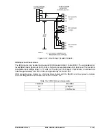
Page 361: ...Figure 12 17 Typical DC Connection Diagrams 9365200990 Rev F BE1 CDS240 Installation 12 17 ...
Page 372: ...12 28 BE1 CDS240 Installation 9365200990 Rev F This page intentionally left blank ...
Page 468: ...13 92 BE1 CDS240 Testing and Maintenance 9365200990 Rev F This page intentionally left blank ...
Page 512: ...14 42 BE1 CDS240 BESTCOMS Software 9365200990 Rev F This page intentionally left blank ...
Page 544: ...ii BE1 CDS240 Terminal Communication 9365200990 Rev F This page intentionally left blank ...
Page 550: ...ii BE1 CDS240 Settings Calculations 9365200990 Rev F This page intentionally left blank ...
Page 578: ...D 28 BE1 CDS240 Settings Calculations 9365200990 Rev F This page intentionally left blank ...
Page 579: ......


