


9365200990 Rev F
BE1-CDS240 Settings Calculations
D-9
Calculate Slope
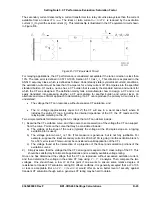
The percentage restrained tripping characteristic is defined by the slope ratio. The slope setting S is the
of
s the ratio of the differential current (
Iop
) caused by the sum of all the mismatch
sources versus the through current. The following sources of
Iop
current must be taken into account:
sis but this does not assure transient DC offset induced
ncel.
i
operating slope value. (These sources of mismatch do not
umed to be less than 4% of the self-cooled rating). This
erate (differential) current that is a result of CT saturation.
For applications where
rgin is recommended.
For applications where
y at high fault current
and the
maximum slope setting (60%)
is recommended. For more information, see Setting Note 4.
In the example, the tap factors were calculated on system nominal ratings so the no load tap changer
position is included as a source of mismatch.
S
i
= (5% NLTC) + (10% LTC) + (10% CT) + (4% Relay) = 29%
ratio of the differential current (
Iop
) versus the restraint current (
Irestraint
) that will cause a trip. The
percentage differential characteristic can operate on a slope setting that is a percent of the maximum
the through currents or a percent of the average of the through currents.
Step 1. Calculate the Operating Slope S
i
.
The operating slope
S
i
i
No load tap changer (this can be compensated for in the tap calculation). You may choose to include
this source of mismatch if it is possible that the no load taps may be adjusted without the relay taps
being reset.
Load tap changer.
Relay tap mismatch (assumed to negligible due to the fine tap adjustment available in the relay).
Quality of the CTs (If the saturation factor calculated previously is greater than 0.5, additional margin
is recommended. For
SF
<0.5, we assume that the CTs perform within the 10% limit defined in the
ANSI Accuracy Class on a steady state ba
saturation will not occur. When accounting for CT error, the total CT error should be 10% * (n-1)
where n is the number of restraint current inputs (2/3/4 for two/three/four restraint relay). If more than
one CT is nearing the performance limit, the errors tend to ca
Relay measuring errors. 4% is the worst case (assume 2% high (or low) on incoming side circuits and
2% low (or high) on outgoing side circuits).
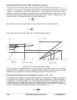
The following errors are not included in the
S
vary with through current so they affect the minpu setting only.)
Transformer excitation current
IE
(ass
mismatch does not vary with through current (load) so it tends to not add to the slope mismatch line.
It will offset the slope characteristic from the origin in the operate direction on the operate versus
restraint characteristic (see Figure D-2).
Unmonitored loads “
Iunmon
” such as station service or small capacitor banks in the differential zone
add to the constant excitation current.
When the saturation factor (
SF
) exceeds 0.5 on any of the CTs, slow clearing transient CT saturation is
likely. For this condition, the BE1-CDS240 improves security by delaying restrained tripping by two cycles
when the transient monitor function detects op
the saturation factor is greater than 0.5, additional slope ma
the saturation factor exceeds 1.0, severe distortion is likel
Summary of Contents for BE1-CDS240
Page 2: ......
Page 8: ...vi BE1 CDS240 Introduction 9365200990 Rev F This page intentionally left blank ...
Page 38: ...1 28 BE1 CDS240 General Information 9365200990 Rev F This page intentionally left blank ...
Page 40: ...ii BE1 CDS240 Quick Start 9365200990 Rev F This page intentionally left blank ...
Page 152: ...ii BE1 CDS240 Metering 9365200990 Rev F This page intentionally left blank ...
Page 226: ...iv BE1 CDS240 Application 9365200990 Rev F This page intentionally left blank ...
Page 286: ...ii BE1 CDS240 Security 9365200990 Rev F This page intentionally left blank ...
Page 290: ...9 4 BE1 CDS240 Security 9365200990 Rev F This page intentionally left blank ...
Page 292: ...ii BE1 CDS240 Human Machine Interface 9365200990 Rev F This page intentionally left blank ...
Page 306: ...10 14 BE1 CDS240 Human Machine Interface 9365200990 Rev F This page intentionally left blank ...
Page 308: ...ii BE1 CDS240 ASCII Command Interface 9365200990 Rev F This page intentionally left blank ...
Page 342: ...11 34 BE1 CDS240 ASCII Command Interface 9365200990 Rev F This page intentionally left blank ...
Page 349: ...Figure 12 5 Horizontal Rack Mount Front View 9365200990 Rev F BE1 CDS240 Installation 12 5 ...
Page 361: ...Figure 12 17 Typical DC Connection Diagrams 9365200990 Rev F BE1 CDS240 Installation 12 17 ...
Page 372: ...12 28 BE1 CDS240 Installation 9365200990 Rev F This page intentionally left blank ...
Page 468: ...13 92 BE1 CDS240 Testing and Maintenance 9365200990 Rev F This page intentionally left blank ...
Page 512: ...14 42 BE1 CDS240 BESTCOMS Software 9365200990 Rev F This page intentionally left blank ...
Page 544: ...ii BE1 CDS240 Terminal Communication 9365200990 Rev F This page intentionally left blank ...
Page 550: ...ii BE1 CDS240 Settings Calculations 9365200990 Rev F This page intentionally left blank ...
Page 578: ...D 28 BE1 CDS240 Settings Calculations 9365200990 Rev F This page intentionally left blank ...
Page 579: ......


