


14.
AMPLITUDE
FIDELITY
TEST
(SA)
Description
This
test
c
hec
ks
the
4395A
amplitude
delity
at
RBW
of
10
kHz.
A
50.1
MHz
CW
signal
is
applied
to
the
4395A
R
input
through
a
step
attenuator.
The
signal
amplitude
is
v
aried
b
y
inserting
kno
wn
attenuation
v
alues.
Eac
h
signal
amplitude
[dB]
is
measured
to
a
reference
v
alue
at
the
attenuator
setting
of
10
dB.
Then
the
measured
v
alues
are
compared
with
to
the
inserted
attenuation's
calibrated
v
alues.
The
amplitude
delity
p erformance
at
RBWs
3
kHz
are
not
tested
in
this
test.
The
error
sources
at
RBW
3
kHz
are
exactly
same
as
those
of
the
magnitude
ratio
dynamic
accuracy
in
the
4395A
net
w
ork
analyzer
mo
de.
Because
the
dynamic
accuracy
is
tested
in
the
Magnitude
R
atio/Phase
Dynamic
A
c
cur
acy
T
est
,
the
delity
test
at
the
RBW
3
kHz
is
omitted.
The
amplitude
delity
p erformance
at
low
signal
lev
els
are
not
tested
in
this
test.
That
is,
the
delity
is
not
c
hec
k
ed
at
signal
lev
els
060
dB
(from
the
reference
lev
el)
at
an
RBW
of
10
kHz
and
at
signal
lev
els
050
dB
(from
the
reference
lev
el)
at
an
RBW
of
1
MHz.
These
tests
are
not
necessary
b ecause
the
delity
p erformance
at
these
lev
els
are
theoretically
determined
b
y
the
delity
at
higher
signal
lev
els
and
the
delity
at
an
RBW
of
3
kHz.
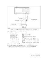
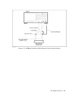
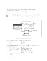
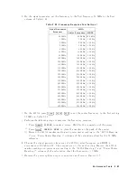
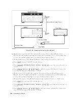
6
and
10
dB
xed
attenuators
with
a
VSWR
of
1.015
are
connected
to
the
signal
generator
output
connector
and
the
4395A
S
input,
resp ectiv
ely
.
These
xed
attenuators
are
used
to
reduce
the
measuremen
t
uncertain
ties
caused
b
y
mismatch
error.
When
they
are
used,
the
measuremen
t
uncertain
ties
listed
in
the
p erformance
test
record
are
v
alid.
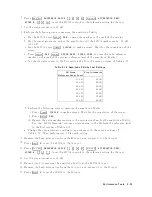
Specification
Amplitude
delit
y
Log
scale
Range
(relativ
e
to
full
scale
input
lev
el)
Amplitude
Fidelity
1
0
dB
range
>
030
dB
60.05
dB
030
dB
>
range
040
dB
60.07
dB
040
dB
>
range
050
dB
60.15
dB
050
dB
>
range
060
dB
60.35
dB
060
dB
>
range
070
dB
60.8
dB
070
dB
>
range
080
dB
61.8
dB
1
@23 65
C,
RBW
=
10
Hz,
020
dBm
r
ef.
value
+30
dBm,
r
ef.
input
level
=
ful
l
sc
ale
input
level
010
dB
T
est
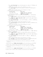
Equipment
Signal
Generator
:
:
:
:
:
:
:
:
:
:
:
:
:
:
:
:
:
:
:
:
:
:
:
:
:
:
:
:
:
:
:
:
:
:
:
:
:
:
:
:
:
:
:
:
:
:
:
:
:
:
:
:
:
:
:
:
:
:
:
:
:
:
:
:
:
:
:
8663A
Step
A
tten
uator
1
,
10
dB
step,
VSWR
1.02
:
:
:
:
:
:
:
:
:
:
:
:
:
:
:
:
:
:
:
:
:
8496G
Opt.
001
and
H60
A
tten
uator
Driv
er
:
:
:
:
:
:
:
:
:
:
:
:
:
:
:
:
:
:
:
:
:
:
:
:
:
:
:
:
:
:
:
:
:
:
:
:
:
:
:
:
:
:
:
:
:
:
:
:
:
:
:
:
:
:
:
:
:
:
:
:
:
:
:
:
:
11713A
T
yp e-N
Cable,
61
cm
(tw
o
required)
:
:
:
:
:
:
:
:
:
:
:
:
:
:
:
:
:
:
:
:
:
:
:
:
:
:
:
:
:
11500B
or
part
of
11851B
BNC
cable,
122
cm
:
:
:
:
:
:
:
:
:
:
:
:
:
:
:
:
:
:
:
:
:
:
:
:
:
:
:
:
:
:
:
:
:
:
:
:
:
:
:
:
:
:
:
:
:
:
:
:
:
:
:
:
:
:
:
:
:
PN
8120-1840
6
dB
Fixed
A
tten
uation,
VSWR
1.015
:
:
:
:
:
:
:
:
:
:
:
:
:
:
:
:
:
:
:
:
:
8491A
Opt.
006
&
Opt.
H60
10
dB
Fixed
A
tten
uation,
VSWR
1.015
:
:
:
:
:
:
:
:
:
:
:
:
:
:
:
:
:
:
:
:
8491A
Opt.
010
&
Opt.
H60
P
erformance
T
ests
2-53
Summary of Contents for 4395A
Page 10: ......
Page 26: ......
Page 34: ......
Page 77: ...Figure 2 17 B R Magnitude Ratio Phase Dynamic Accuracy Test Setup 2 Performance Tests 2 43 ...
Page 167: ...Figure 5 1 Adjustment Hardware Setup Adjustments 5 5 ...
Page 186: ...Figure 5 13 Receiver Gain Adjustment Location 5 24 Adjustments ...
Page 190: ...Figure 5 16 Receiver Flatness Adjustment Setup 1 MHz 5 28 Adjustments ...
Page 194: ...Figure 5 20 DC Bias Adjustment Setup 2 5 32 Adjustments ...
Page 196: ...Figure 6 1 Troubleshooting Organization 6 2 Troubleshooting ...
Page 206: ...Figure 7 1 Power Supply Lines Simplified Block Diagram 7 2 Power Supply Troubleshooting ...
Page 212: ...Figure 7 5 A1 CPU Connector Locations 7 8 Power Supply Troubleshooting ...
Page 220: ...Figure 8 1 Digital Control Group Simplified Block Diagram 8 2 Digital Control Troubleshooting ...
Page 240: ...Figure 10 1 Top View Major Assemblies 10 4 Replaceable Parts ...
Page 292: ...Table A 2 Manual Changes by Firmware Version Version Make Manual Changes A 2 Manual Changes ...
Page 308: ......
Page 311: ...Figure B 1 Power Cable Supplied Power Requirement B 3 ...
Page 312: ......
Page 342: ......


