


11
P
ost
Repair
Procedures
INTRODUCTION
This
c
hapter
lists
the
pro cedures
required
to
v
erify
the
analyzer
op eration
after
an
assem
bly
is
replaced
with
a
new
one.
POST
REP
AIR
PROCEDURES
T
able
11-1
Post
R
ep
air
Pr
o
c
e
dur
es
lists
the
required
pro cedures
that
m
ust
b e
p erformed
after
the
replacemen
t
of
an
assem
bly
or
the
EEPR
OM.
These
are
the
recommended
minimum
pro cedures
to
ensure
that
the
analyzer
is
w
orking
prop erly
follo wing
the
replacemen
t.
When
y
ou
replace
an
assem
bly
or
the
EEPR
OM
on
the
A1
CPU,
p erform
the
adjustmen
ts
and
up dating
correction
constan
ts
listed
in
T
able
11-1.
Then
p erform
the
op erational
v
erications
and
p erformance
v
erications
listed
in
T
able
11-1.
F
or
the
detailed
pro cedure
of
the
adjustmen
ts
and
up dating
correction
constan
ts,
see
the
A
djustments
c
hapter.
F
or
the
detailed
op erational
v
erication
pro cedures,
see
this
man
ual's
c
hapter
sp ecied
in
T
able
11-1 .
F
or
the
detailed
p erformance
v
erication
pro cedures,
see
the
Performanc
e
T
ests
c
hapter.
T
able
11-1.
P
ost
Repair
Procedures
Replaced
Assembly
or
P
art
Adjustments
Correction
Constants
V
erication
A1
CPU
Firm
w
are
Installation.
1
INSPECT
THE
PO
WER
ON
SEQUENCE
2
Internal
T
est
2:
A1
V
OLA
TILE
MEMOR
Y
2
A1
EEPR
OM
Lo
cal
D
A
C
Adjustmen t
INSPECT
THE
PO
WER
ON
SEQUENCE
2
Source
P
ow
er
Adjustmen t
All
P
erformance
T
est
Items
Source
Flatness
Adjustmen t
IF
8
dB/16
dB
Gain
Adjustmen t
IF
Gain
Error
CC
T
emprature
Adjustmen t
Receiv er
Flatness
Adjustmen t
Receiv er
A
ttnuator
Adjustmen
t
IF
BPF
Flatness
Adjustmen
t
DC
Bias
Adjustmen
t
1
See
the
Digital
Contr
ol
T
r
oublesho
oting
c
hapter.
2
See
the
T
r
oublesho
oting
c
hapter.
P
ost
Repair
Procedures
11-1
Summary of Contents for 4395A
Page 10: ......
Page 26: ......
Page 34: ......
Page 77: ...Figure 2 17 B R Magnitude Ratio Phase Dynamic Accuracy Test Setup 2 Performance Tests 2 43 ...
Page 167: ...Figure 5 1 Adjustment Hardware Setup Adjustments 5 5 ...
Page 186: ...Figure 5 13 Receiver Gain Adjustment Location 5 24 Adjustments ...
Page 190: ...Figure 5 16 Receiver Flatness Adjustment Setup 1 MHz 5 28 Adjustments ...
Page 194: ...Figure 5 20 DC Bias Adjustment Setup 2 5 32 Adjustments ...
Page 196: ...Figure 6 1 Troubleshooting Organization 6 2 Troubleshooting ...
Page 206: ...Figure 7 1 Power Supply Lines Simplified Block Diagram 7 2 Power Supply Troubleshooting ...
Page 212: ...Figure 7 5 A1 CPU Connector Locations 7 8 Power Supply Troubleshooting ...
Page 220: ...Figure 8 1 Digital Control Group Simplified Block Diagram 8 2 Digital Control Troubleshooting ...
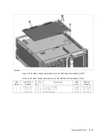
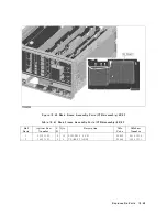
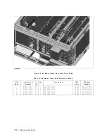
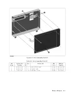
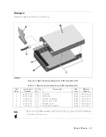
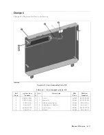
Page 240: ...Figure 10 1 Top View Major Assemblies 10 4 Replaceable Parts ...
Page 292: ...Table A 2 Manual Changes by Firmware Version Version Make Manual Changes A 2 Manual Changes ...
Page 308: ......
Page 311: ...Figure B 1 Power Cable Supplied Power Requirement B 3 ...
Page 312: ......
Page 342: ......


