


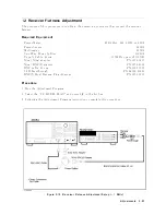


9.
Receiv
er
Gain
Adjustment
The
purp ose
of
this
pro cedure
is
to
adjust
the
total
gain
of
the
receiv
er.
Note
HP
VEE
Adjustmen
t
Program
is
not
required
in
this
adjustmen
t.
F
ollo
w
the
pro cedures
b elow
and
adjust
prop er
item
using
the
in
ternal
adjustmen
t
test.
Required
Equipment
Signal
Generator
:
:
:
:
:
:
:
:
:
:
:
:
:
:
:
:
:
:
:
:
:
:
:
:
:
:
:
:
:
:
:
:
:
:
:
:
:
:
:
:
:
:
:
:
:
:
:
:
:
:
:
:
:
8642B/8644B/8663A
P
o
w
er
Meter
:
:
:
:
:
:
:
:
:
:
:
:
:
:
:
:
:
:
:
:
:
:
:
:
:
:
:
:
:
:
:
:
:
:
:
:
:
:
:
:
:
:
:
:
:
:
:
436A
Opt.
022,
437B,
or
438A
P
o
w
er
Sensor
:
:
:
:
:
:
:
:
:
:
:
:
:
:
:
:
:
:
:
:
:
:
:
:
:
:
:
:
:
:
:
:
:
:
:
:
:
:
:
:
:
:
:
:
:
:
:
:
:
:
:
:
:
:
:
:
:
:
:
:
:
:
:
:
:
:
:
:
:
:
:
8482A
Tw
o-W
a
y
P
o
w
er
Splitter
:
:
:
:
:
:
:
:
:
:
:
:
:
:
:
:
:
:
:
:
:
:
:
:
:
:
:
:
:
:
:
:
:
:
:
:
:
:
:
:
:
:
:
:
:
:
:
:
:
:
:
:
:
:
:
:
:
:
:
11667A
T
yp e-N
Cable,
61
cm
:
:
:
:
:
:
:
:
:
:
:
:
:
:
:
:
:
:
:
:
:
:
:
:
:
:
:
:
:
:
:
:
:
:
:
:
:
:
:
:
:
:
:
:
11500B
or
part
of
11851B
N(m)-N(m)
adapter
:
:
:
:
:
:
:
:
:
:
:
:
:
:
:
:
:
:
:
:
:
:
:
:
:
:
:
:
:
:
:
:
:
:
:
:
:
:
:
:
:
:
:
:
:
:
:
:
:
:
:
:
:
:
:
:
:
PN
1250-1475
Procedure
1.
T
urn
the
4395A
OFF.
2.
T
o
gain
access
to
the
adjustmen
t
comp onen
ts,
remov
e
the
top
co
v
er
of
the
4395A.
3.
T
urn
the
4395A
ON.
4.
Press
4
System
5,
NNNNNNNNNNNNNNNNNNNNNNNNNNNNNNNNNNNNNNNNN
SERVICE
TESTS
,
NNNNNNNNNNNNNNNNNNNNNNNNNNNNNNNNNNNNNNNNNNNNNNNNNN
ADJUSTMENT
TESTS
to
display
the
in
ternal
adjustmen
t
tests
men
u.
5.
Press
4
6
5,
4
7
5
or
use
4
*
5/ 4
+
5
to
select
the
in
ternal
adjustmen
t
test
67:
A7
GAIN
ADJ.
6.
Press
NNNNNNNNNNNNNNNNNNNNNNNNNNNNNNNNNNNNNN
EXECUTE
TEST
to
run
the
test.
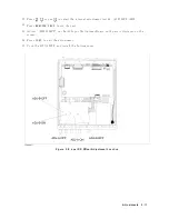
7.
Connect
the
test
equipmen
t
as
sho
wn
in
the
Figure
5-12.
5-22
Adjustments
Summary of Contents for 4395A
Page 10: ......
Page 26: ......
Page 34: ......
Page 77: ...Figure 2 17 B R Magnitude Ratio Phase Dynamic Accuracy Test Setup 2 Performance Tests 2 43 ...
Page 167: ...Figure 5 1 Adjustment Hardware Setup Adjustments 5 5 ...
Page 186: ...Figure 5 13 Receiver Gain Adjustment Location 5 24 Adjustments ...
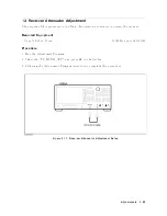
Page 190: ...Figure 5 16 Receiver Flatness Adjustment Setup 1 MHz 5 28 Adjustments ...
Page 194: ...Figure 5 20 DC Bias Adjustment Setup 2 5 32 Adjustments ...
Page 196: ...Figure 6 1 Troubleshooting Organization 6 2 Troubleshooting ...
Page 206: ...Figure 7 1 Power Supply Lines Simplified Block Diagram 7 2 Power Supply Troubleshooting ...
Page 212: ...Figure 7 5 A1 CPU Connector Locations 7 8 Power Supply Troubleshooting ...
Page 220: ...Figure 8 1 Digital Control Group Simplified Block Diagram 8 2 Digital Control Troubleshooting ...
Page 240: ...Figure 10 1 Top View Major Assemblies 10 4 Replaceable Parts ...
Page 292: ...Table A 2 Manual Changes by Firmware Version Version Make Manual Changes A 2 Manual Changes ...
Page 308: ......
Page 311: ...Figure B 1 Power Cable Supplied Power Requirement B 3 ...
Page 312: ......
Page 342: ......


