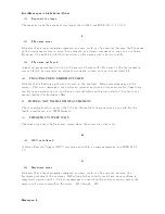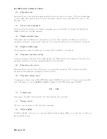
Error
Messages
in
Numerical
Order
17
BA
CKUP
D
A
T
A
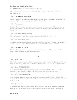
LOST
Data
c
hec
ksum
error
on
the
battery
bac
kup
memory
has
o ccurred.
The
battery
is
rec
harged
for
appro
ximately
10
min
utes
after
p o
w
er
w
as
turned
on .
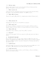
19
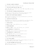
UNEXPECTED
D
A
T
A
DETECTED:
CAL
ABOR
TED
The
signal
measured
for
the
lev
el
cal
is
not
adequate
for
the
calibration
signal.
(sp ectrum
analyzer
mo
de
only
.)
26
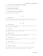
PRINTER:not
on,
not
connect,
wrong
address
The
prin
ter
do es
not
resp ond
to
con
trol.
Chec
k
the
supply
to
the
prin
ter,
online
status,
sheets,
and
so
on.
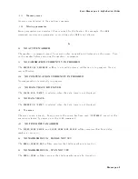
34
NO
V
ALID
MEMOR
Y
TRACE
If
a
memory
trace
is
to
b e
display
ed
or
otherwise
used,
a
data
trace
m
ust
rst
b e
stored
to
memory
.
37
DISPLA
Y
BUFFER
IS
FULL
The
display
buer
is
lled
with
the
o
v
erlay
traces
or
traces
dra
wn
b
y
IBASIC
DRA
W/MOVE
commands,
etc.
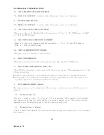
44
O
VERLO
AD
ON
INPUT
B
The
p o
w
er
lev
el
at
one
of
the
four
receiv
er
inputs
exceeds
a
certain
lev
el
greater
than
the
maximum
input
lev
el.
45
O
VERLO
AD
ON
INPUT
A
The
p o
w
er
lev
el
at
one
of
the
four
receiv
er
inputs
exceeds
a
certain
lev
el
greater
than
the
maximum
input
lev
el.
46
O
VERLO
AD
ON
INPUT
R
The
p o
w
er
lev
el
at
one
of
the
four
receiv
er
inputs
exceeds
a
certain
lev
el
greater
than
the
maximum
input
lev
el.
48
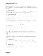
PHASE
LOCK
LOOP
UNLOCKED
EXT
REF
Input
of
10
MHz
is
not
prop er,
or
the
instrumen
t
is
needed
to
adjust
or
repair.
Chec
k
the
external
reference
signal
rst.
Con
tact
y
our
nearest
Agilent
T
ec
hnologies
oce
for
adjustmen
t
or
repair.
Messages-17
Summary of Contents for 4395A
Page 10: ......
Page 26: ......
Page 34: ......
Page 77: ...Figure 2 17 B R Magnitude Ratio Phase Dynamic Accuracy Test Setup 2 Performance Tests 2 43 ...
Page 167: ...Figure 5 1 Adjustment Hardware Setup Adjustments 5 5 ...
Page 186: ...Figure 5 13 Receiver Gain Adjustment Location 5 24 Adjustments ...
Page 190: ...Figure 5 16 Receiver Flatness Adjustment Setup 1 MHz 5 28 Adjustments ...
Page 194: ...Figure 5 20 DC Bias Adjustment Setup 2 5 32 Adjustments ...
Page 196: ...Figure 6 1 Troubleshooting Organization 6 2 Troubleshooting ...
Page 206: ...Figure 7 1 Power Supply Lines Simplified Block Diagram 7 2 Power Supply Troubleshooting ...
Page 212: ...Figure 7 5 A1 CPU Connector Locations 7 8 Power Supply Troubleshooting ...
Page 220: ...Figure 8 1 Digital Control Group Simplified Block Diagram 8 2 Digital Control Troubleshooting ...
Page 240: ...Figure 10 1 Top View Major Assemblies 10 4 Replaceable Parts ...
Page 292: ...Table A 2 Manual Changes by Firmware Version Version Make Manual Changes A 2 Manual Changes ...
Page 308: ......
Page 311: ...Figure B 1 Power Cable Supplied Power Requirement B 3 ...
Page 312: ......
Page 342: ......


