


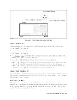


Figure
9-1.
Probe
P
o
w
er
Connector
V
oltages
Inspect
the
T
est
Set
This
pro cedure
c
hec
ks
the
op eration
of
the
RF
transfer
switch
in
the
85046A/B
test
set.
1.
T
urn
the
analyzer
p o
w
er
o.
2.
Connect
the
test
set
to
the
analyzer.
3.
T
urn
the
analyzer
p o
w
er
on.
4.
Press
4
PRESET
5,
4
Meas
5,
NNNNNNNNNNNNNNNNNNNNNNNNNNNNNNNNNNNNNNNNN
ANALYZER
TYPE
,
NNNNNNNNNNNNNNNNNNNNNNNNNNNNNNNNNNNNNNNNNNNNNNNNNN
NETWORK
ANALYZER
,
NNNNNNNNNNNNNNNNNNNNNNNNNNNNNNNNNNNNNNNNNNNNNNNNNNNNNNNN
Refl:
REV
S22(B/R)
.
Then
c
hec
k
that
the
S22
S12
indicator
LED
lits.
5.
Press
NNNNNNNNNNNNNNNNNNNNNNNNNNNNNNNNNNNNNNNNNNNNNNNNNNNNNNNNNNN
Refl:
FWD
S11
(A/R)
.
Chec
k
that
the
S11
S21
indicator
LED
lits.
If
the
LED
op erations
are
not
exp ected,
insp ect
the
cable
b et
w
een
the
analyzer
and
the
test
set.
If
the
cable
seems
go
o d,
v
erify
the
test
set
in
accordance
with
its
man
ual.
If
the
LED
op erations
are
correct,
con
tinue
with
this
c
hapter
unless
a
test
set
failure
is
susp ected.
T
o
troublesho
ot
test
set
failures,
see
the
test
set
man
ual.
Inspect
the
Calibration
Kit
Insp ect
all
of
the
terminations
(load,
op en,
and
short)
for
an
y
damage.
If
no
damage
is
found,
p erform
the
follo wing
pro cedure
to
v
erify
the
short
and
op en.
If
an
y
damage
is
found,
replace
the
termination
with
a
go
o d
one.
V
erify
Shorts
and
Opens
Substitute
a
kno
wn
go
o d
short
and
op en
of
the
same
connector
t
yp e
as
the
terminations
in
question.
If
the
devices
are
not
from
a
standard
calibration
kit,
see
Mo
difying
Calibr
ation
Kits
in
the
F
unction
R
efer
enc
e
to
use
the
NNNNNNNNNNNNNNNNNNNNNNNNNNNNNNNNNNNNNNNNNNNNNNNNNN
MODIFY
[CAL
KIT]
function.
Set
aside
the
short
and
op en
that
could
b e
causing
the
problem.
Accessories
Troubleshooting
9-5
Summary of Contents for 4395A
Page 10: ......
Page 26: ......
Page 34: ......
Page 77: ...Figure 2 17 B R Magnitude Ratio Phase Dynamic Accuracy Test Setup 2 Performance Tests 2 43 ...
Page 167: ...Figure 5 1 Adjustment Hardware Setup Adjustments 5 5 ...
Page 186: ...Figure 5 13 Receiver Gain Adjustment Location 5 24 Adjustments ...
Page 190: ...Figure 5 16 Receiver Flatness Adjustment Setup 1 MHz 5 28 Adjustments ...
Page 194: ...Figure 5 20 DC Bias Adjustment Setup 2 5 32 Adjustments ...
Page 196: ...Figure 6 1 Troubleshooting Organization 6 2 Troubleshooting ...
Page 206: ...Figure 7 1 Power Supply Lines Simplified Block Diagram 7 2 Power Supply Troubleshooting ...
Page 212: ...Figure 7 5 A1 CPU Connector Locations 7 8 Power Supply Troubleshooting ...
Page 220: ...Figure 8 1 Digital Control Group Simplified Block Diagram 8 2 Digital Control Troubleshooting ...
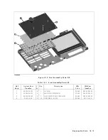
Page 240: ...Figure 10 1 Top View Major Assemblies 10 4 Replaceable Parts ...
Page 292: ...Table A 2 Manual Changes by Firmware Version Version Make Manual Changes A 2 Manual Changes ...
Page 308: ......
Page 311: ...Figure B 1 Power Cable Supplied Power Requirement B 3 ...
Page 312: ......
Page 342: ......


