


13.
DISPLA
YED
A
VERA
GE
NOISE
LEVEL
TEST
(SA)
Description
This
test
uses
the
4395A
marker
statistics
function
to
measure
the
display
ed
a
v
erage
noise
lev
el
in
the
4395A
sp ectrum
analyzer
mo
de.
In
this
test,
the
noise
lev
el
(trace
mean
v
alue)
is
measured
in
linear
format
[W
att].
Then
the
measured
v
alues
are
con
v
erted
to
log
magnitude
format
[dBm].
This
is
done
to
a
v
oid
sk
ewing
the
data
with
the
marker
statistics
function.
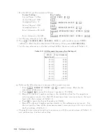
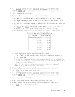
Specification
Display
ed
a
v
erage
noise
lev
el
freq.
1
kHz,
ref.
lev
el
040
dBm,
att.=0
dB
:
:
:
:
:
:
:
:
:
:
:
:
:
:
:
:
:
:
:
:
:
:
:
<
0120
dBm/Hz
freq.
100
kHz,
ref.
lev
el
040
dBm,
att.=0
dB
:
:
:
:
:
:
:
:
:
:
:
:
:
:
:
:
:
:
:
:
:
<
0133
dBm/Hz
freq.
10
MHz,
ref.
lev
el
040
dBm,
att.=0
dB
:
:
:
:
:
:
:
:
:
:
:
<[
0145+ f
1
/100]
dBm/Hz
1:
f
is
measurement
frequency
(MHz).
T
est
Equipment
50
T
ermination
(three
required)
:
:
:
:
:
:
:
:
:
:
:
:
:
:
:
:
:
:
:
:
:
:
:
:
909C
Opt.
012
or
part
of
85032B
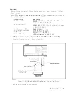
Procedure
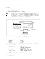
1.
Connect
the
test
equipmen
t
as
sho
wn
in
Figure
2-20.
Figure
2-20.
Av
erage
Noise
Lev
el
T
est
Setup
2-50
P
erformance
T
ests
Summary of Contents for 4395A
Page 10: ......
Page 26: ......
Page 34: ......
Page 77: ...Figure 2 17 B R Magnitude Ratio Phase Dynamic Accuracy Test Setup 2 Performance Tests 2 43 ...
Page 167: ...Figure 5 1 Adjustment Hardware Setup Adjustments 5 5 ...
Page 186: ...Figure 5 13 Receiver Gain Adjustment Location 5 24 Adjustments ...
Page 190: ...Figure 5 16 Receiver Flatness Adjustment Setup 1 MHz 5 28 Adjustments ...
Page 194: ...Figure 5 20 DC Bias Adjustment Setup 2 5 32 Adjustments ...
Page 196: ...Figure 6 1 Troubleshooting Organization 6 2 Troubleshooting ...
Page 206: ...Figure 7 1 Power Supply Lines Simplified Block Diagram 7 2 Power Supply Troubleshooting ...
Page 212: ...Figure 7 5 A1 CPU Connector Locations 7 8 Power Supply Troubleshooting ...
Page 220: ...Figure 8 1 Digital Control Group Simplified Block Diagram 8 2 Digital Control Troubleshooting ...
Page 240: ...Figure 10 1 Top View Major Assemblies 10 4 Replaceable Parts ...
Page 292: ...Table A 2 Manual Changes by Firmware Version Version Make Manual Changes A 2 Manual Changes ...
Page 308: ......
Page 311: ...Figure B 1 Power Cable Supplied Power Requirement B 3 ...
Page 312: ......
Page 342: ......


