


Preparation
for
Using
the
Adjustment
Program
T
o
use
the
4395A
adjustmen
t
program,
it
is
rst
necessary
to
install
an
GPIB
Card.
This
section
describ es
ho
w
to
install
it.
Installing
an
GPIB
Card
(82340
or
82341)
Install
an
GPIB
Card
in
y
our
computer
(see
the
GPIB
Card
man
ual).
The
select
co de
of
the
GPIB
Card
should
b e
set
to
\7".
The
GPIB
Card
should
b e
the
82340
or
84321.
Other
GPIB
Cards
can
not
b e
used
in
the
Windows
NT
en
vironmen
t.
Installing
HP
VEE
for
Windo
ws
NT
Install
the
HP
VEE
for
Windows
NT
in
y
our
computer
(see
the
HP
VEE
for
Windows
NT
man
ual).
After
installing
HP
VEE
for
Windows
NT,
run
the
Congur
e
I/O
utility
in
the
HP
VEE
for
Windows
NT
group
b
y
double-clic
king
on
its
icon
to
c
hec
k
that
the
GPIB
In
terface
Board
is
correctly
installed.
Installing
Adjustment
Program
into
Y
our
PC
Make
a
directory
named
4395A
on
the
C
driv
e
and
cop
y
the
4395A
adjustmen
t
program
under
the
created
directory
.
Getting
Started
1.
Start
the
HP
VEE
b
y
clic
king
the
HP
VEE
icon
on
y
our
PC.
2.
Load
the
adjustmen
t
program
le
in
to
the
HP
VEE
as
follo
ws:
a.
Pull
do
wn
the
File
men
u
from
the
HP
VEE
windo
w
and
select
File
-
Open .
b.
Select
the
le
C:\4395A\ADJUST.VEE
.
c.
Press
NNNNNNNN
OK
.
Note
Y
ou
may
b e
asked
GPIB
addresses
of
the
test
equipmen
t
during
the
program
loading.
En
ter
the
address
for
eac
h
equipmen
t.
En
ter
0
as
the
address
for
the
equipmen
t
whic
h
are
not
used
for
the
adjustmen
t
test.
3.
Press
NNNNNNNNNNNNNNNNN
Start
button
on
the
Adjustmen
t
Program
screen.
4.
In
the
\Setup"
windo
w,
mo
dify
the
settings
if
required.
5.
Press
NNNNNNNN
OK
.
6.
Mo
dify
the
calibration
factor
of
the
8482A
in
the
windo
w.
7.
Press
NNNNNNNN
OK
.
8.
Select
the
mo
del
n
um
b er
and
press
NNNNNNNN
OK
.
5-6
Adjustments
Summary of Contents for 4395A
Page 10: ......
Page 26: ......
Page 34: ......
Page 77: ...Figure 2 17 B R Magnitude Ratio Phase Dynamic Accuracy Test Setup 2 Performance Tests 2 43 ...
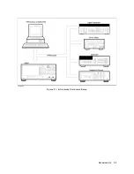
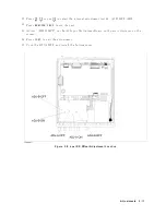
Page 167: ...Figure 5 1 Adjustment Hardware Setup Adjustments 5 5 ...
Page 186: ...Figure 5 13 Receiver Gain Adjustment Location 5 24 Adjustments ...
Page 190: ...Figure 5 16 Receiver Flatness Adjustment Setup 1 MHz 5 28 Adjustments ...
Page 194: ...Figure 5 20 DC Bias Adjustment Setup 2 5 32 Adjustments ...
Page 196: ...Figure 6 1 Troubleshooting Organization 6 2 Troubleshooting ...
Page 206: ...Figure 7 1 Power Supply Lines Simplified Block Diagram 7 2 Power Supply Troubleshooting ...
Page 212: ...Figure 7 5 A1 CPU Connector Locations 7 8 Power Supply Troubleshooting ...
Page 220: ...Figure 8 1 Digital Control Group Simplified Block Diagram 8 2 Digital Control Troubleshooting ...
Page 240: ...Figure 10 1 Top View Major Assemblies 10 4 Replaceable Parts ...
Page 292: ...Table A 2 Manual Changes by Firmware Version Version Make Manual Changes A 2 Manual Changes ...
Page 308: ......
Page 311: ...Figure B 1 Power Cable Supplied Power Requirement B 3 ...
Page 312: ......
Page 342: ......


