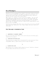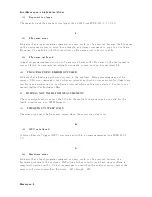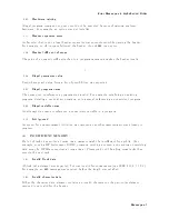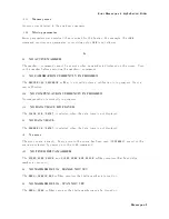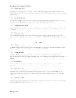
Error
Messages
in
Alphabetical
Order
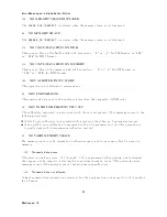
R
111
RECALL
ERR
OR:
INSTR
ST
A
TE
PRESET
A
serious
error,
for
example
corrupted
data,
is
detected
on
recalling
a
le,
and
this
forced
the
analyzer
to
b e
PRESET.
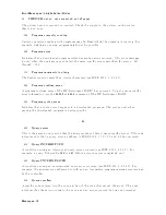
S
110
SA
VE
ERR OR
A
serious
error,
for
example
ph
ysically
damaged
disk
surface,
is
detected
on
sa
ving
a
le.
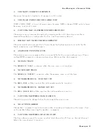
76
SEGMENT
ST
AR
T/STOP
O
VERLAPPED
Segmen
ts
are
not
allo
w
ed
to
b e
o
v
erlapp ed.
Reen
ter
appropriate
v
alue
for
start
or
stop
v
alue
of
segmen
ts
to
a
v
oid
that
segmen
t
is
not
o
v
erlapp ed.
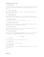
0330
Self-test
failed
A
self-test
failed.
Con
tact
y
our
nearest
Agilent
T
ec
hnologies
oce
or
see
the
Servic
e
Manual
for
troublesho
oting.
0221
Settings
conict
A
legal
program
data
elemen
t
w
as
parsed
but
could
not
b e
executed
due
to
the
curren
t
device
state
(see
IEEE
488.2,
6.4.5.3
and
11.5.1.1.5).
128
SP
AN
=
0
ONL
Y
The
setup
m
ust
b e
zero
span
and
sp ectrum
analyzer
mo
de
when
turning
on
the
RF
OUTPUT.
0150
String
data
error
This
error,
as
w
ell
as
errors
0151
and
0158,
are
generated
when
analyzing
the
syn
tax
of
a
string
data
elemen
t.
This
particular
error
message
is
used
if
the
analyzer
cannot
detect
a
more
sp ecic
error.
0158
String
data
not
allow
ed
A
string
data
elemen
t
w
as
encoun
tered
but
w
as
not
allo
w
ed
b
y
the
analyzer
at
this
p oint
in
parsing.
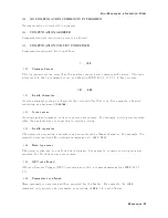
0130
Sux
error
This
error,
as
w
ell
as
errors
0131
through
0139,
are
generated
when
parsing
a
sux.
This
particular
error
message
is
used
if
the
analyzer
cannot
detect
a
more
sp ecic
error.
Messages-13
Summary of Contents for 4395A
Page 10: ......
Page 26: ......
Page 34: ......
Page 77: ...Figure 2 17 B R Magnitude Ratio Phase Dynamic Accuracy Test Setup 2 Performance Tests 2 43 ...
Page 167: ...Figure 5 1 Adjustment Hardware Setup Adjustments 5 5 ...
Page 186: ...Figure 5 13 Receiver Gain Adjustment Location 5 24 Adjustments ...
Page 190: ...Figure 5 16 Receiver Flatness Adjustment Setup 1 MHz 5 28 Adjustments ...
Page 194: ...Figure 5 20 DC Bias Adjustment Setup 2 5 32 Adjustments ...
Page 196: ...Figure 6 1 Troubleshooting Organization 6 2 Troubleshooting ...
Page 206: ...Figure 7 1 Power Supply Lines Simplified Block Diagram 7 2 Power Supply Troubleshooting ...
Page 212: ...Figure 7 5 A1 CPU Connector Locations 7 8 Power Supply Troubleshooting ...
Page 220: ...Figure 8 1 Digital Control Group Simplified Block Diagram 8 2 Digital Control Troubleshooting ...
Page 240: ...Figure 10 1 Top View Major Assemblies 10 4 Replaceable Parts ...
Page 292: ...Table A 2 Manual Changes by Firmware Version Version Make Manual Changes A 2 Manual Changes ...
Page 308: ......
Page 311: ...Figure B 1 Power Cable Supplied Power Requirement B 3 ...
Page 312: ......
Page 342: ......


