


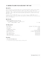


7.
RECEIVER
NOISE
LEVEL
TEST
(NA)
Description
This
test
measures
the
4395A
receiv
er
noise
lev
els
(noise
o or)
in
the
net
w
ork
analyzer
mo
de
at
IF
BW
10
Hz.
This
measures
the
noise
lev
el
using
the
marker
statistics
function
(mean)
when
the
inputs
are
terminated.
In
this
test,
the
noise
lev
el
(trace
mean
v
alue)
is
measured
in
linear
format
[Unit].
Then
the
measured
v
alues
are
con
v
erted
to
log
magnitude
format
[dBm].
This
is
done
to
a
v
oid
sk
ewing
the
data
with
the
marker
statistics
function.
Specification
Noise
lev
el
Noise
Lev
el
F
requency
@IFBW=10
Hz
100
freq.
<
100
kHz
<085
dBm
100
kHz
freq.
<[
0115
+
f
1
/100
]
dBm
1:
f
is
measurement
frequency
(MHz).
T
est
Equipment
50
T
ermination
(three
required)
:
:
:
:
:
:
:
:
:
:
:
:
:
:
:
:
:
:
:
:
:
:
:
:
909C
Opt.
012
or
part
of
85032B
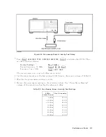
Procedure
1.
Connect
the
test
equipmen
t
as
sho
wn
in
Figure
2-9.
Figure
2-9.
Receiv
er
Noise
Lev
el
T
est
Setup
P
erformance
T
ests
2-21
Summary of Contents for 4395A
Page 10: ......
Page 26: ......
Page 34: ......
Page 77: ...Figure 2 17 B R Magnitude Ratio Phase Dynamic Accuracy Test Setup 2 Performance Tests 2 43 ...
Page 167: ...Figure 5 1 Adjustment Hardware Setup Adjustments 5 5 ...
Page 186: ...Figure 5 13 Receiver Gain Adjustment Location 5 24 Adjustments ...
Page 190: ...Figure 5 16 Receiver Flatness Adjustment Setup 1 MHz 5 28 Adjustments ...
Page 194: ...Figure 5 20 DC Bias Adjustment Setup 2 5 32 Adjustments ...
Page 196: ...Figure 6 1 Troubleshooting Organization 6 2 Troubleshooting ...
Page 206: ...Figure 7 1 Power Supply Lines Simplified Block Diagram 7 2 Power Supply Troubleshooting ...
Page 212: ...Figure 7 5 A1 CPU Connector Locations 7 8 Power Supply Troubleshooting ...
Page 220: ...Figure 8 1 Digital Control Group Simplified Block Diagram 8 2 Digital Control Troubleshooting ...
Page 240: ...Figure 10 1 Top View Major Assemblies 10 4 Replaceable Parts ...
Page 292: ...Table A 2 Manual Changes by Firmware Version Version Make Manual Changes A 2 Manual Changes ...
Page 308: ......
Page 311: ...Figure B 1 Power Cable Supplied Power Requirement B 3 ...
Page 312: ......
Page 342: ......


