


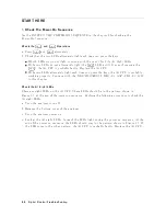


5.
Check
the
A30
Front
Keyboard
The
A30
fron
t
k
eyb oard
can
b e
c
hec
k
ed
using
the
external
test
50:
FR
ONT
P
ANEL
DIA
G.
a.
Press
4
PRESET
5,
4
SYSTEM
5,
NNNNNNNNNNNNNNNNNNNNNNNNNNNNNNNNNNNNNN
SERVICE
MENU
,
NNNNNNNNNNNNNNNNN
TESTS
,
4
5
5,
4
0
5,
4
x1
5,
NNNNNNNNNNNNNNNNNNNNNNNNNNNNNNNNNNNNNN
EXECUTE
TEST
to
run
the
external
test
17.
b.
Press
all
of
the
fron
t
panel
k
eys.
The
pressed
abbreviated
k
ey
name
should
b e
display
ed
at
a
k
ey
pressed.
When
y
ou
rotate
the
RPG
knob,
the
RPG
tuned
direction
(CW
or
CCW)
and
its
resp onse
sp eed
(SLO
W,
MID,
F
AST)
should
b e
display
ed.
So
y
ou
can
c
hec
k
ev
ery
k
ey
on
the
A30
Keyb oard
except
for
4
PRESET
5.
(If
y
ou
w
an
t
to
exit
this
test,
press
4
PRESET
5.)
If
one
or
more
k
eys
seems
to
b e
defectiv
e,
replace
the
A30
fron
t
k
eyb oard.
If
all
k
eys
seem
to
b e
go
o d,
the
A30
fron
t
k
eyb oard
is
v
eried.
Con
tin
ue
with
the
next
Che
ck
the
A53
FDD
.
6.
Check
the
A53
FDD
The
A53
FDD
(Flexible
Disk
Drive)
can
b e
c
hec
k
ed
using
the
external
test
51:
DSK
DR
F
ALUT
ISOL'N.
a.
Press
4
PRESET
5,
4
SYSTEM
5,
NNNNNNNNNNNNNNNNNNNNNNNNNNNNNNNNNNNNNN
SERVICE
MENU
,
NNNNNNNNNNNNNNNNN
TESTS
,
4
5
5,
4
1
5,
4
x1
5,
NNNNNNNNNNNNNNNNNNNNNNNNNNNNNNNNNNNNNN
EXECUTE
TEST
to
run
the
external
test
51.
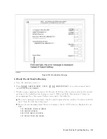
b.
As
the
analyzer
instructs,
insert
a
exible
disk
in
to
FDD.
Use
a
formatted
but
blank
exible
disk,
otherwise
the
data
on
the
disk
will
b e
o
v
erwritten
b
y
this
test.
Then
press
NNNNNNNNNNNNNN
CONT
.
c.
Chec
k
the
test
result,
P
ASS
or
F
AIL,
that
is
display
ed
at
the
end
of
the
test.
If
this
test
fails,
replace
the
A53
FDD.
7.
Check
the
A32
I-BASIC
Interface
and
the
mini
DIN
Keyboard
The
mini
DIN
external
k
eyb oard
is
connected
to
the
A32
I-BASIC
I/O
connector,
and
is
used
to
dev
elop
programs.
If
the
external
k
eyb oard
of
the
I-Basic
is
not
w
orking,
p erform
the
follo wing
pro cedure
to
v
erify
the
k
eyb oard.
Press
4
PRESET
5,
4
SYSTEM
5,
NNNNNNNNNNNNNNNNNNNNNNNNNNNNNNNNNNNNNN
SERVICE
MENU
,
NNNNNNNNNNNNNNNNN
TESTS
,
4
1
5,
4
x1
5,
NNNNNNNNNNNNNNNNNNNNNNNNNNNNNNNNNNNNNN
EXECUTE
TEST
to
run
the
in
ternal
test
1:
A1
CPU.
If
the
in
ternal
test
1
passes,
the
Agilent
driv
er
circuit
on
the
A1
CPU
is
probably
w
orking.
Insp ect
cables
b et
w
een
the
external
k
eyb oard
and
the
A1
CPU
through
the
A32
I-BASIC
in
terface.
If
the
cable
is
go
o d,
replace
the
external
k
eyb oard.
If
the
in
ternal
test
1
fails,
replace
the
A1
CPU.
8-10
Digital
Control
Troubleshooting
Summary of Contents for 4395A
Page 10: ......
Page 26: ......
Page 34: ......
Page 77: ...Figure 2 17 B R Magnitude Ratio Phase Dynamic Accuracy Test Setup 2 Performance Tests 2 43 ...
Page 167: ...Figure 5 1 Adjustment Hardware Setup Adjustments 5 5 ...
Page 186: ...Figure 5 13 Receiver Gain Adjustment Location 5 24 Adjustments ...
Page 190: ...Figure 5 16 Receiver Flatness Adjustment Setup 1 MHz 5 28 Adjustments ...
Page 194: ...Figure 5 20 DC Bias Adjustment Setup 2 5 32 Adjustments ...
Page 196: ...Figure 6 1 Troubleshooting Organization 6 2 Troubleshooting ...
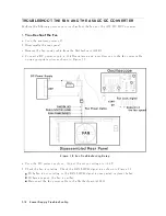
Page 206: ...Figure 7 1 Power Supply Lines Simplified Block Diagram 7 2 Power Supply Troubleshooting ...
Page 212: ...Figure 7 5 A1 CPU Connector Locations 7 8 Power Supply Troubleshooting ...
Page 220: ...Figure 8 1 Digital Control Group Simplified Block Diagram 8 2 Digital Control Troubleshooting ...
Page 240: ...Figure 10 1 Top View Major Assemblies 10 4 Replaceable Parts ...
Page 292: ...Table A 2 Manual Changes by Firmware Version Version Make Manual Changes A 2 Manual Changes ...
Page 308: ......
Page 311: ...Figure B 1 Power Cable Supplied Power Requirement B 3 ...
Page 312: ......
Page 342: ......


