


VERIFY
OPERA
TIONS
The
measuremen
t
problem
can
b e
caused
b
y
improp
er
op eration.
Conrm
that
all
op erations,
connections
and
con
trol
settings,
etc.,
are
prop erly
made
during
the
measuremen
t.
F
or
detailed
information
ab out
prop er
op erations,
see
the
follo wing
man
uals:
Op
er
ation
Manual
(p/n
04395-90000)
Pr
o
gr
amming
Manual
(p/n
04395-90000)
Some
examples
of
the
t
ypical
op eration
errors
are
sho
wn
in
the
follo wing
paragraph.
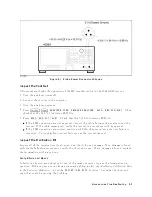
Using
75
Connectors
with
50
Connectors
Do
not
use
50
connectors
with
75
connectors;
their
cen
ter
conductors
are
dieren
t
diameters.
Using
a
50
male
connector
with
a
75
female
connector
will
destroy
the
female
connector.
Large
Spurious
Signals
in
the
Spectrum
Measurement
Large
spurious
signals
around
the
fundamen
tal
signal
can
b e
caused
b
y
an
input
signal
lev
el
that
is
higher
than
the
reference
lev
el.
Reducing
the
input
signal
lev
el
or
setting
the
reference
lev
el
higher
can
solve
the
spurious
signal
problem.
Odd
Appearing
Opens
and
Shorts
in
the
Netw
ork
Measurement
Op ens
and
shorts
can
app ear
as
short
lines
(rather
than
the
exp ected
p oints)
on
a
Smith
Chart.
This
is
a
result
of
some
shorts
and
op ens
b eing
oset.
See
the
calibration
kit
man
ual
to
determine
the
oset.
T
o
v
erify
the
op ens
and
shorts,
see
V
erify
Shorts
and
Op
ens
in
the
Insp
e
ct
the
Calibr
ation
Kit
pro cedure
later
in
this
c
hapter.
9-2
Accessories
Troubleshooting
Summary of Contents for 4395A
Page 10: ......
Page 26: ......
Page 34: ......
Page 77: ...Figure 2 17 B R Magnitude Ratio Phase Dynamic Accuracy Test Setup 2 Performance Tests 2 43 ...
Page 167: ...Figure 5 1 Adjustment Hardware Setup Adjustments 5 5 ...
Page 186: ...Figure 5 13 Receiver Gain Adjustment Location 5 24 Adjustments ...
Page 190: ...Figure 5 16 Receiver Flatness Adjustment Setup 1 MHz 5 28 Adjustments ...
Page 194: ...Figure 5 20 DC Bias Adjustment Setup 2 5 32 Adjustments ...
Page 196: ...Figure 6 1 Troubleshooting Organization 6 2 Troubleshooting ...
Page 206: ...Figure 7 1 Power Supply Lines Simplified Block Diagram 7 2 Power Supply Troubleshooting ...
Page 212: ...Figure 7 5 A1 CPU Connector Locations 7 8 Power Supply Troubleshooting ...
Page 220: ...Figure 8 1 Digital Control Group Simplified Block Diagram 8 2 Digital Control Troubleshooting ...
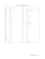
Page 240: ...Figure 10 1 Top View Major Assemblies 10 4 Replaceable Parts ...
Page 292: ...Table A 2 Manual Changes by Firmware Version Version Make Manual Changes A 2 Manual Changes ...
Page 308: ......
Page 311: ...Figure B 1 Power Cable Supplied Power Requirement B 3 ...
Page 312: ......
Page 342: ......


