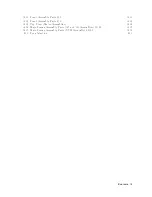
5-13.
Receiv
er
Gain
Adjustmen
t
Lo cation
.
.
.
.
.
.
.
.
.
.
.
.
.
.
.
.
.
.
5-24
5-14.
IF
8
dB/16
dB
Gain
Adjustmen
t
Setup
.
.
.
.
.
.
.
.
.
.
.
.
.
.
.
.
5-25
5-15.
Receiv
er
Flatness
Adjustmen
t
Setup
( <
1
MHz)
.
.
.
.
.
.
.
.
.
.
.
.
5-27
5-16.
Receiv
er
Flatness
Adjustmen
t
Setup
(
1
MHz)
.
.
.
.
.
.
.
.
.
.
.
.
5-28
5-17.
Receiv
er
A
tten
uator
Adjustmen
t
Setup
.
.
.
.
.
.
.
.
.
.
.
.
.
.
.
.
5-29
5-18.
IF
BPF
Flatness
Adjustmen
t
Setup
.
.
.
.
.
.
.
.
.
.
.
.
.
.
.
.
.
.
5-30
5-19.
DC
Bias
Adjustmen
t
Setup
1
.
.
.
.
.
.
.
.
.
.
.
.
.
.
.
.
.
.
.
.
.
5-31
5-20.
DC
Bias
Adjustmen
t
Setup
2
.
.
.
.
.
.
.
.
.
.
.
.
.
.
.
.
.
.
.
.
.
5-32
6-1.
T
roublesho oting
Organization
.
.
.
.
.
.
.
.
.
.
.
.
.
.
.
.
.
.
.
.
6-2
7-1.
P
o
w
er
Supply
Lines
Simplied
Blo
c
k
Diagram
.
.
.
.
.
.
.
.
.
.
.
.
.
7-2
7-2.
A50
SHUTDO
WN
LED
Lo cation
.
.
.
.
.
.
.
.
.
.
.
.
.
.
.
.
.
.
.
7-3
7-3.
A1
+5
VD
LED
Lo cation
.
.
.
.
.
.
.
.
.
.
.
.
.
.
.
.
.
.
.
.
.
.
7-4
7-4.
Remo
ving
Line
F
use
.
.
.
.
.
.
.
.
.
.
.
.
.
.
.
.
.
.
.
.
.
.
.
.
.
7-6
7-5.
A1
CPU
Connector
Lo cations
.
.
.
.
.
.
.
.
.
.
.
.
.
.
.
.
.
.
.
.
7-8
7-6.
A40J1
Output
V
oltage
.
.
.
.
.
.
.
.
.
.
.
.
.
.
.
.
.
.
.
.
.
.
.
.
7-9
7-7.
A1
CPU
Connector
Lo cations
.
.
.
.
.
.
.
.
.
.
.
.
.
.
.
.
.
.
.
.
7-10
7-8.
F
an
T
roublesho oting
Setup
.
.
.
.
.
.
.
.
.
.
.
.
.
.
.
.
.
.
.
.
.
.
7-12
7-9.
A50
DC-DC
Con
v
erter
T
roublesho oting
Setup
.
.
.
.
.
.
.
.
.
.
.
.
.
7-13
8-1.
Digital
Con
trol
Group
Simplied
Blo
c
k
Diagram
.
.
.
.
.
.
.
.
.
.
.
.
8-2
8-2.
A1
EEPR
OM
Lo cation
.
.
.
.
.
.
.
.
.
.
.
.
.
.
.
.
.
.
.
.
.
.
.
8-3
8-3.
Firm
w
are
Revision
Lab el
.
.
.
.
.
.
.
.
.
.
.
.
.
.
.
.
.
.
.
.
.
.
.
8-4
8-4.
Bo otloader
Men
u
Display
.
.
.
.
.
.
.
.
.
.
.
.
.
.
.
.
.
.
.
.
.
.
8-5
8-5.
A1
Eight
LEDs'
P
attern
.
.
.
.
.
.
.
.
.
.
.
.
.
.
.
.
.
.
.
.
.
.
.
8-7
8-6.
Bo otloader
Displa
y
.
.
.
.
.
.
.
.
.
.
.
.
.
.
.
.
.
.
.
.
.
.
.
.
.
8-9
9-1.
Prob e
P
o
w
er
Connector
V
oltages
.
.
.
.
.
.
.
.
.
.
.
.
.
.
.
.
.
.
.
9-5
10-1.
T
op
View
(Ma
jor
Assem
blies)
.
.
.
.
.
.
.
.
.
.
.
.
.
.
.
.
.
.
.
.
10-4
10-2.
Bottom
View
(Ma
jor
Assem
blies)
.
.
.
.
.
.
.
.
.
.
.
.
.
.
.
.
.
.
.
10-6
10-3.
Angle
Assem
bly
P
arts
1/5
.
.
.
.
.
.
.
.
.
.
.
.
.
.
.
.
.
.
.
.
.
.
10-7
10-4.
Angle
Assem
bly
P
arts
2/5
.
.
.
.
.
.
.
.
.
.
.
.
.
.
.
.
.
.
.
.
.
.
10-8
10-5.
Angle
Assem
bly
P
arts
(Opt.
001)
3/5
.
.
.
.
.
.
.
.
.
.
.
.
.
.
.
.
.
10-9
10-6.
Angle
Assem
bly
P
arts
4/5
.
.
.
.
.
.
.
.
.
.
.
.
.
.
.
.
.
.
.
.
.
.
10-10
10-7.
Angle
Assem
bly
P
arts
5/5
.
.
.
.
.
.
.
.
.
.
.
.
.
.
.
.
.
.
.
.
.
.
10-11
10-8.
F
ron
t
Assem
bly
P
arts
1/8
.
.
.
.
.
.
.
.
.
.
.
.
.
.
.
.
.
.
.
.
.
.
10-12
10-9.
F
ron
t
Assem
bly
P
arts
2/8
.
.
.
.
.
.
.
.
.
.
.
.
.
.
.
.
.
.
.
.
.
.
10-13
10-10.
F
ron
t
Assem
bly
P
arts
3/8
.
.
.
.
.
.
.
.
.
.
.
.
.
.
.
.
.
.
.
.
.
.
10-14
10-11.
F
ron
t
Assem
bly
P
arts
4/8
.
.
.
.
.
.
.
.
.
.
.
.
.
.
.
.
.
.
.
.
.
.
10-15
10-12.
F
ron
t
Assem
bly
P
arts
5/8
.
.
.
.
.
.
.
.
.
.
.
.
.
.
.
.
.
.
.
.
.
.
10-16
10-13.
F
ron
t
Assem
bly
P
arts
6/8
.
.
.
.
.
.
.
.
.
.
.
.
.
.
.
.
.
.
.
.
.
.
10-17
10-14.
F
ron
t
Assem
bly
P
arts
7/8
.
.
.
.
.
.
.
.
.
.
.
.
.
.
.
.
.
.
.
.
.
.
10-18
10-15.
F
ron
t
Assem
bly
P
arts
8/8
.
.
.
.
.
.
.
.
.
.
.
.
.
.
.
.
.
.
.
.
.
.
10-19
10-16.
Rear
Assem
bly
P
arts
1/8
.
.
.
.
.
.
.
.
.
.
.
.
.
.
.
.
.
.
.
.
.
.
10-20
10-17.
Rear
Assem
bly
P
arts
2/8
.
.
.
.
.
.
.
.
.
.
.
.
.
.
.
.
.
.
.
.
.
.
10-21
10-18.
Rear
Assem
bly
P
arts
3/8
.
.
.
.
.
.
.
.
.
.
.
.
.
.
.
.
.
.
.
.
.
.
10-22
10-19.
Rear
Assem
bly
P
arts
4/8
.
.
.
.
.
.
.
.
.
.
.
.
.
.
.
.
.
.
.
.
.
.
10-23
10-20.
Rear
Assem
bly
P
arts
5/8
.
.
.
.
.
.
.
.
.
.
.
.
.
.
.
.
.
.
.
.
.
.
10-24
10-21.
Rear
Assem
bly
P
arts
(Opt.
1D5)
6/8
.
.
.
.
.
.
.
.
.
.
.
.
.
.
.
.
.
10-25
10-22.
Rear
Assem
bly
P
arts
7/8
.
.
.
.
.
.
.
.
.
.
.
.
.
.
.
.
.
.
.
.
.
.
10-26
10-23.
Rear
Assem
bly
P
arts
8/8
.
.
.
.
.
.
.
.
.
.
.
.
.
.
.
.
.
.
.
.
.
.
10-27
10-24.
Main
F
rame
Assem
bly
P
arts
1/23
.
.
.
.
.
.
.
.
.
.
.
.
.
.
.
.
.
.
.
10-28
10-25.
Main
F
rame
Assem
bly
P
arts
2/23
.
.
.
.
.
.
.
.
.
.
.
.
.
.
.
.
.
.
.
10-29
10-26.
Main
F
rame
Assem
bly
P
arts
(FDD
Assem
bly)
3/23
.
.
.
.
.
.
.
.
.
.
.
10-30
Contents-11
Summary of Contents for 4395A
Page 10: ......
Page 26: ......
Page 34: ......
Page 77: ...Figure 2 17 B R Magnitude Ratio Phase Dynamic Accuracy Test Setup 2 Performance Tests 2 43 ...
Page 167: ...Figure 5 1 Adjustment Hardware Setup Adjustments 5 5 ...
Page 186: ...Figure 5 13 Receiver Gain Adjustment Location 5 24 Adjustments ...
Page 190: ...Figure 5 16 Receiver Flatness Adjustment Setup 1 MHz 5 28 Adjustments ...
Page 194: ...Figure 5 20 DC Bias Adjustment Setup 2 5 32 Adjustments ...
Page 196: ...Figure 6 1 Troubleshooting Organization 6 2 Troubleshooting ...
Page 206: ...Figure 7 1 Power Supply Lines Simplified Block Diagram 7 2 Power Supply Troubleshooting ...
Page 212: ...Figure 7 5 A1 CPU Connector Locations 7 8 Power Supply Troubleshooting ...
Page 220: ...Figure 8 1 Digital Control Group Simplified Block Diagram 8 2 Digital Control Troubleshooting ...
Page 240: ...Figure 10 1 Top View Major Assemblies 10 4 Replaceable Parts ...
Page 292: ...Table A 2 Manual Changes by Firmware Version Version Make Manual Changes A 2 Manual Changes ...
Page 308: ......
Page 311: ...Figure B 1 Power Cable Supplied Power Requirement B 3 ...
Page 312: ......
Page 342: ......

