


Required
T
est
Equipment
Required
equipmen
t
for
p erforming
the
adjustmen
ts
is
listed
in
T
able
5-1 .
Use
only
calibrated
test
equipmen
t
when
adjusting
the
4395A.
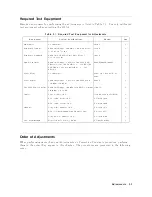
T
able
5-1.
Required
T
est
Equipment
for
Adjustments
Equipmen
t
Critical
Sp
ecications
Mo del
Qty
Multimeter
No
substitute
3458A
1
F
requency
Counter
F
requency
Range:
500
MHz,Time
Base
Error:
61.9 210
07
/year
5334B
1
F
requency
Standard
F
requency:
10
MHz,Time
Base
Error:
61 210
010
/year
5061B
1
Signal
Generator
F
requency
Range
:
1
MHz
to
500
MHz,
SSB
Phase
Noise
at
100
Hz
oset:
<
0112
dBc/Hz,
SSB
Phase
Noise
at
1
kHz
oset:
<
0121
dBc/Hz
8642B/8644B/8663A
1
P
ow
er
Meter
No
substitute
436A
Opt.
022,
437B,
or
438A
1
P
ow
er
Sensor
F
requency
Range
:
1
MHz
to
500
MHz,P
ow
er:
026
dBm
to
0
dBm
8482A
1
Tw
o-W
ay
P
ow
er
Splitter
F
requency
Range:
100
kHz
to
500
MHz,
Output
T
racking:
0.15
dB
11667A
1
Cables
T
yp
e-N
cable,
50
11500B
or
part
of
11851B
1
BNC
cable,
61
cm,
50
PN
8120-1839
1
BNC
cable,
122
cm,
50
PN
8120-1840
1
Adapters
N(m)-N(m)
adapter,
50
PN
1250-1475
1
BNC(f
)-Dual
Banana
Plug
Adapter,
50
PN
1251-2277
1
N(m)-BNC(f
)
adapter,
50
PN
1250-0780
1
50
F
eedthrough
Rejection
at
75
MHz:
60
dB
PN
04192-61002
1
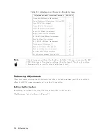
Order
of
Adjustments
When
p erforming
more
than
one
Adjustmen
ts
or
Correction
Constants
pro cedure,
p erform
them
in
the
order
they
app ear
in
this
c
hapter.
The
pro cedures
are
presen
ted
in
the
follo wing
order:
Adjustments
5-3
Summary of Contents for 4395A
Page 10: ......
Page 26: ......
Page 34: ......
Page 77: ...Figure 2 17 B R Magnitude Ratio Phase Dynamic Accuracy Test Setup 2 Performance Tests 2 43 ...
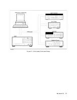
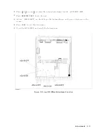
Page 167: ...Figure 5 1 Adjustment Hardware Setup Adjustments 5 5 ...
Page 186: ...Figure 5 13 Receiver Gain Adjustment Location 5 24 Adjustments ...
Page 190: ...Figure 5 16 Receiver Flatness Adjustment Setup 1 MHz 5 28 Adjustments ...
Page 194: ...Figure 5 20 DC Bias Adjustment Setup 2 5 32 Adjustments ...
Page 196: ...Figure 6 1 Troubleshooting Organization 6 2 Troubleshooting ...
Page 206: ...Figure 7 1 Power Supply Lines Simplified Block Diagram 7 2 Power Supply Troubleshooting ...
Page 212: ...Figure 7 5 A1 CPU Connector Locations 7 8 Power Supply Troubleshooting ...
Page 220: ...Figure 8 1 Digital Control Group Simplified Block Diagram 8 2 Digital Control Troubleshooting ...
Page 240: ...Figure 10 1 Top View Major Assemblies 10 4 Replaceable Parts ...
Page 292: ...Table A 2 Manual Changes by Firmware Version Version Make Manual Changes A 2 Manual Changes ...
Page 308: ......
Page 311: ...Figure B 1 Power Cable Supplied Power Requirement B 3 ...
Page 312: ......
Page 342: ......


